Toyota Corolla Cross: Installation
INSTALLATION
CAUTION / NOTICE / HINT
COMPONENTS (INSTALLATION)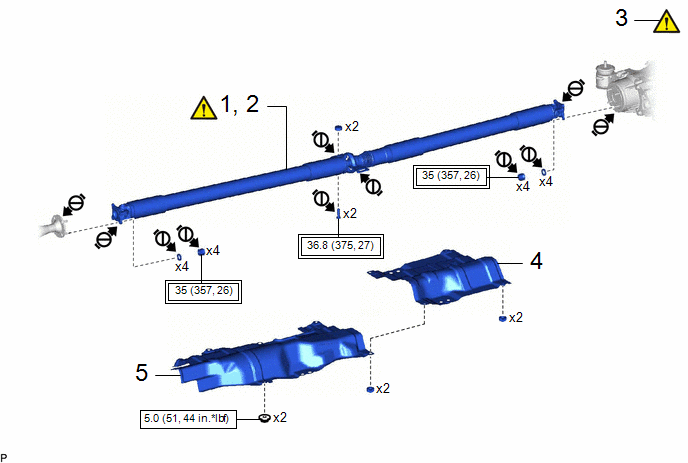
|
Procedure |
Part Name Code |
.png) |
.png) |
.png) |
|
|---|---|---|---|---|---|
|
1 |
TEMPORARILY INSTALL PROPELLER SHAFT WITH CENTER BEARING ASSEMBLY |
37100 |
|
- |
- |
|
2 |
FULLY TIGHTEN PROPELLER SHAFT WITH CENTER BEARING ASSEMBLY |
37100 |
|
- |
- |
|
3 |
INSPECT AND ADJUST JOINT ANGLE |
- |
|
- |
- |
|
4 |
FRONT NO. 2 FLOOR HEAT INSULATOR |
58153 |
- |
- |
- |
|
5 |
FRONT LOWER NO. 1 FLOOR HEAT INSULATOR |
58152A |
- |
- |
- |
.png) |
Tightening torque for "Major areas involving basic vehicle performance such as moving/turning/stopping": N*m (kgf*cm, ft.*lbf) |
.png) |
N*m (kgf*cm, ft.*lbf): Specified torque |
.png) |
Do not apply lubricants to the threaded parts |
- |
- |
|
Procedure |
Part Name Code |
|
|
|
|
|---|---|---|---|---|---|
|
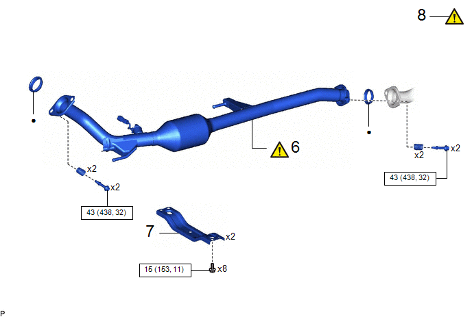
6 |
FRONT EXHAUST PIPE ASSEMBLY |
17410 |
|
- |
- |
|
7 |
FRONT FLOOR CENTER BRACE |
57533B |
- |
- |
- |
|
8 |
INSPECT FOR EXHAUST GAS LEAK |
- |
|
- |
- |
|
|
N*m (kgf*cm, ft.*lbf): Specified torque |
● |
Non-reusable part |
PROCEDURE
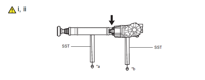
1. TEMPORARILY INSTALL PROPELLER SHAFT WITH CENTER BEARING ASSEMBLY
|
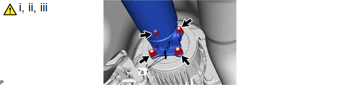
*a |
Matchmark |
- |
- |
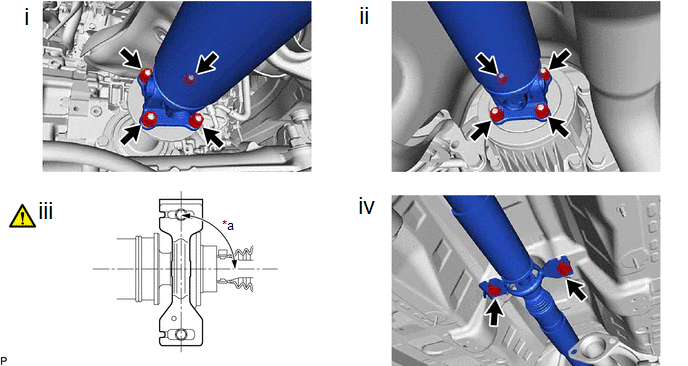
(1) Completely remove any oil or the like and clean the contact surfaces of the rear differential carrier assembly and propeller shaft with center bearing assembly.
(2) Align the matchmarks on the rear differential carrier assembly and propeller shaft with center bearing assembly.
(3) Temporarily install the propeller shaft with center bearing assembly to the rear differential carrier assembly with the 4 nuts and 4 washers.
NOTICE:
Make sure there is no oil on the nuts and washers. If oil is found on any nut and washer, clean it before installation.
|
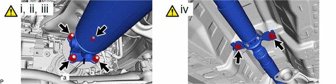
*a |
Matchmark |
- |
- |
(1) Completely remove any oil or the like and clean the contact surfaces of the transfer assembly and propeller shaft with center bearing assembly.
(2) Align the matchmarks of the transfer assembly and propeller shaft with center bearing assembly.
(3) Temporarily install the propeller shaft with center bearing assembly to the transfer assembly with the 4 nuts and 4 washers.
NOTICE:
Make sure there is no oil on the nuts and washers. If oil is found on any nut and washer, clean it before installation.
(4) Temporarily install the center support bearing with the 2 bolts and 2 center No. 2 support bearing washers.
NOTICE:
Make sure there is no oil on the nuts and center No. 2 support bearing washers. If oil is found on any nut and center No. 2 support bearing washer, clean it before installation.
2. FULLY TIGHTEN PROPELLER SHAFT WITH CENTER BEARING ASSEMBLY
|
*a |
90° |
- |
- |
(1) Fully tighten the 4 nuts.
Torque:
35 N·m {357 kgf·cm, 26 ft·lbf}
(2) Fully tighten the 4 nuts.
Torque:
35 N·m {357 kgf·cm, 26 ft·lbf}
(3) Check that the center line of the center support bearing housing is perpendicular to the axis of the propeller shaft.
(4) Fully tighten the 2 bolts.
Torque:
36.8 N·m {375 kgf·cm, 27 ft·lbf}
3. INSPECT AND ADJUST JOINT ANGLE
|
|
NOTICE: Perform the measurement with a 4 post lift or pit so that the vehicle is supported by all 4 wheels as if it were on the ground. |
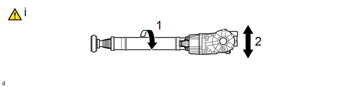
(1) Before the angle measurement, stabilize each part by performing procedures like those described below.
1. Rotate the propeller shaft assembly several times by hand.
2. Set the jack to the rear differential carrier assembly, and raise and lower the rear differential carrier assembly.
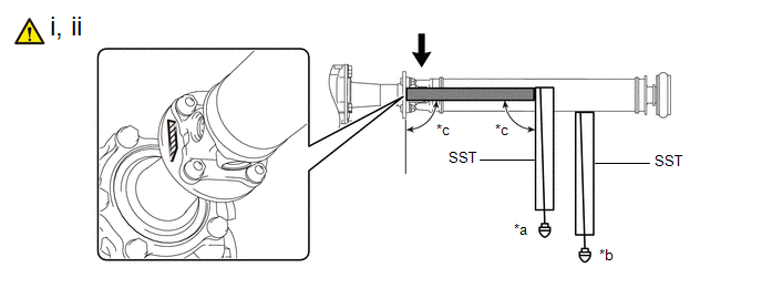
|
*a |
Angle D |
*b |
Angle A |
|
*c |
90° |
- |
- |
.png) |
No. 1 Joint Angle (D - A) |
.png) |
Straightedge |
 |
Angle D Measurement Position |
- |
- |
(1) Using SST and a straightedge, measure the angle of the transfer flange (angle D) and the angle of the intermediate shaft assembly (angle A).
SST: 09370-50010
NOTICE:
Make sure the straightedge and SST are at a right angle.
(2) Subtract the measured angle of the intermediate shaft assembly (angle A) from the measured angle of the transfer flange (angle D) to obtain the No. 1 joint angle.
Standard No. 1 Joint Angle:
|
Measurement Position |
Angle |
|---|---|
|
D - A |
-2°28' +/- 30' |
|
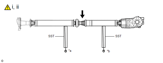
*a |
Angle A |
*b |
Angle B |
|
|
No. 2 Joint Angle (A - B) |
- |
- |
(1) Using SST, measure the angle of the intermediate shaft assembly (angle A) and the angle of the propeller shaft assembly (angle B).
SST: 09370-50010
(2) Subtract the measured angle of the propeller shaft assembly (angle B) from the measured angle of the intermediate shaft assembly (angle A) to obtain the No. 2 joint angle.
Standard No. 2 Joint Angle:
|
Measurement Position |
Angle |
|---|---|
|
A - B |
1°54' +/- 30' |
|
*a |
Angle B |
*b |
Angle C |
|
|
No. 3 Joint Angle (B - C) |
- |
- |
(1) Using SST, measure the angle of the propeller shaft assembly (angle B) and the angle of the rear differential carrier assembly (angle C).
SST: 09370-50010
(2) Subtract the measured angle of the rear differential carrier assembly (angle C) from the measured angle of the propeller shaft assembly (angle B) to obtain the No. 3 joint angle.
Standard No. 3 Joint Angle:
|
Measurement Position |
Angle |
|---|---|
|
B - C |
2°06' +/- 30' |
(1) If the measured angle of the propeller shaft with center bearing assembly is not within the specified range, or there is vibration or noise, use the following procedure to adjust the propeller shaft with center bearing assembly.
1. Support the propeller shaft with center bearing assembly with a jack.
2. Remove the 2 center support bearing mounting bolts.
3. Slowly lower the jack and separate the center support bearing.
4. Select an appropriate adjusting washer thickness from the table below, and obtain a washer set.
Adjusting Washer|
Part No. |
Thickness |
|---|---|
|
90201-10123 |
2.0 mm (0.0787 in.) |
|
90201-10081 |
4.5 mm (0.177 in.) |
|
90201-10083 |
6.5 mm (0.256 in.) |
|
90201-10084 |
9.0 mm (0.354 in.) |
|
90201-10085 |
11.0 mm (0.433 in.) |
NOTICE:
- Use washers of the same thickness on the left and right sides.
- Do not use 2 or more washers stacked together.
4. INSTALL FRONT NO. 2 FLOOR HEAT INSULATOR
5. INSTALL FRONT LOWER NO. 1 FLOOR HEAT INSULATOR
Torque:
5.0 N·m {51 kgf·cm, 44 in·lbf}
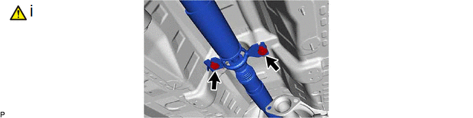
6. INSTALL FRONT EXHAUST PIPE ASSEMBLY
|
|
Click here |
7. INSTALL FRONT FLOOR CENTER BRACE
Click here .gif)
8. INSPECT FOR EXHAUST GAS LEAK
Click here


