Toyota Corolla Cross: Right Side Restraints Sensor 5 Value of Signal Protection Calculation Incorrect (B009E83)
DESCRIPTION
|
DTC No. | Detection Item |
DTC Detection Condition | Trouble Area |
Warning Indicate | Test Mode / Check Mode |
|---|---|---|---|---|---|
|
B009E83 | Right Side Restraints Sensor 5 Value of Signal Protection Calculation Incorrect |
One of the following conditions is met:
|
| Comes on |
Not applicable |
|
Vehicle Condition | |||||||
|---|---|---|---|---|---|---|---|
|
Pattern 1 | Pattern 2 |
Pattern 3 | Pattern 4 |
Pattern 5 | Pattern 6 | ||
|
Diagnosis Condition | Ignition switch ON |
○ | ○ |
○ | ○ |
○ | ○ |
|
Malfunction Status | The airbag ECU assembly detects a line short circuit signal in the side collision sensor RH circuit (bus 1). |
○ | - |
- | - |
- | - |
|
The airbag ECU assembly detects an open circuit signal in the side collision sensor RH circuit (bus 1). |
- | ○ |
- | - |
- | - | |
|
The airbag ECU assembly detects a short circuit to ground signal in the side collision sensor RH circuit (bus 1). |
- | - |
○ | - |
- | - | |
|
The airbag ECU assembly detects a short circuit to B+ signal in the side collision sensor RH circuit (bus 1). |
- | - |
- | ○ |
- | - | |
|
Side airbag pressure sensor RH malfunction |
- | - |
- | - |
○ | - | |
|
Airbag ECU assembly malfunction |
- | - |
- | - |
- | ○ | |
|
Detection Time | 2 seconds |
2 seconds | 2 seconds |
2 seconds | 2 seconds |
2 seconds | |
|
Number of Trips | 1 trip |
1 trip | 1 trip |
1 trip | 1 trip |
1 trip | |
HINT:
DTC will be output when conditions for either of the patterns in the table above are met.
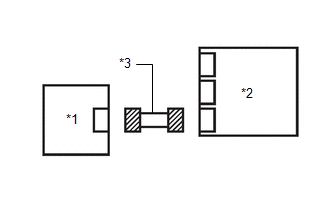
WIRING DIAGRAM
.png)
CAUTION / NOTICE / HINT
NOTICE:
- After the ignition switch is turned off, there may be a waiting time before disconnecting the negative (-) battery terminal.
Click here
.gif)
HINT:
When disconnecting and reconnecting the battery, there is an automatic learning function that completes learning when the respective system is used.
Click here
- After replacing the airbag ECU assembly, refer to initialization.
Click here
PROCEDURE
|
1. | CHECK CONNECTION OF CONNECTORS |
(a) Turn the ignition switch off.
(b) Disconnect the cable from the negative (-) battery terminal.
CAUTION:
Wait at least 60 seconds after disconnecting the cable from the negative (-) battery terminal to disable the SRS system.
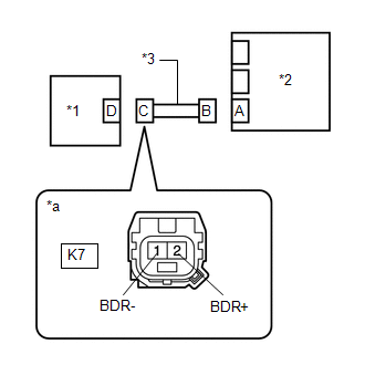
(c) Check that the connectors are properly connected to the airbag ECU assembly and side airbag pressure sensor RH.
OK:
The connectors are properly connected.
| NG | .gif) | CONNECT CONNECTORS PROPERLY |
|
.gif)
| 2. |
CHECK CONNECTORS |
(a) Disconnect the connectors from the airbag ECU assembly and side airbag pressure sensor RH.
| (b) Check that the terminals of the connectors are not deformed or damaged. OK: The terminals of the connectors are not deformed or damaged. |
|
| NG | | REPAIR OR REPLACE HARNESS OR CONNECTOR |
|
| 3. |
CHECK HARNESS AND CONNECTOR (SHORT) |
| (a) Measure the resistance according to the value(s) in the table below. Standard Resistance:
|
|
| NG | | REPAIR OR REPLACE HARNESS OR CONNECTOR |
|
| 4. |
CHECK HARNESS AND CONNECTOR (SHORT TO GROUND) |
| (a) Measure the resistance according to the value(s) in the table below. Standard Resistance:
|
|
| NG | | REPAIR OR REPLACE HARNESS OR CONNECTOR |
|
| 5. |
CHECK HARNESS AND CONNECTOR (SHORT TO B+) |
(a) Connect the cable to the negative (-) battery terminal.
(b) Turn the ignition switch to ON.
| (c) Measure the voltage according to the value(s) in the table below. Standard Voltage:
Result:
|
|
(d) Turn the ignition switch off.
(e) Disconnect the cable from the negative (-) battery terminal.
CAUTION:
Wait at least 60 seconds after disconnecting the cable from the negative (-) battery terminal to disable the SRS system.
| NG | | REPAIR OR REPLACE HARNESS OR CONNECTOR |
|
| 6. |
CHECK HARNESS AND CONNECTOR (OPEN) |
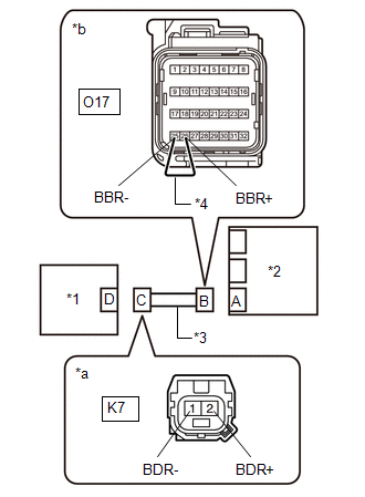
(a) Using a service wire, connect terminals 26 (BBR+) and 25 (BBR-) of connector B.
NOTICE:
Do not forcibly insert the service wire into the terminals of the connector when connecting the wire.
| (b) Measure the resistance according to the value(s) in the table below. Standard Resistance:
Result:
|
|
(c) Disconnect the service wire from connector B.
| NG | | REPAIR OR REPLACE HARNESS OR CONNECTOR |
|
| 7. |
CLEAR DTC |
| (a) Connect the connector to the airbag ECU assembly. |
|
.png)
(b) Interchange the side airbag pressure sensor RH with LH and connect the connectors.
(c) Connect the cable to the negative (-) battery terminal.
(d) Turn the ignition switch to ON, and wait for at least 60 seconds.
(e) Clear the DTCs stored in memory.
Body Electrical > SRS Airbag > Clear DTCs(f) Turn the ignition switch off.
|
| 8. |
CHECK SIDE AIRBAG PRESSURE SENSOR RH |
(a) Turn the ignition switch to ON, and wait for at least 60 seconds.
(b) Check for DTCs.
Body Electrical > SRS Airbag > Trouble Codes| Result |
Proceed to |
|---|---|
| B009E83 is output |
A |
| B009B83 is output |
B |
| B009B83 and B009E83 are not output |
C |
HINT:
Codes other than DTCs B009E83 and B009B83 may be output at this time, but they are not related to this check.
(c) Turn the ignition switch off.
(d) Disconnect the cable from the negative (-) battery terminal.
CAUTION:
Wait at least 60 seconds after disconnecting the cable from the negative (-) battery terminal to disable the SRS system.
(e) Return the side airbag pressure sensor RH and LH to their original positions and connect the connectors.
| A |
| REPLACE AIRBAG ECU ASSEMBLY |
| B |
| REPLACE SIDE AIRBAG PRESSURE SENSOR RH |
| C |
| USE SIMULATION METHOD TO CHECK |
READ NEXT:
 Right Side Restraints Sensor 5 Signal Below Allowable Range (B009E84)
DESCRIPTION
DTC No. Detection Item
DTC Detection Condition Trouble Area
Warning Indicate Test Mode / Check Mode
B009E84 Right Side Restraints Sensor 5 Signal Below Allo
Right Side Restraints Sensor 5 Signal Above Allowable Range (B009E85)
DESCRIPTION
DTC No. Detection Item
DTC Detection Condition Trouble Area
Warning Indicate Test Mode / Check Mode
B009E85 Right Side Restraints Sensor 5 Signal Above Allo
Right Side Restraints Sensor 5 Missing Message (B009E87)
DESCRIPTION
DTC No. Detection Item
DTC Detection Condition Trouble Area
Warning Indicate Test Mode / Check Mode
B009E87 Right Side Restraints Sensor 5 Missing Message
SEE MORE:
 Inner Rear View Mirror (w/o Ec Mirror)
RemovalREMOVAL CAUTION / NOTICE / HINT COMPONENTS (REMOVAL)
Procedure Part Name Code
1 NO. 2 FORWARD RECOGNITION COVER
86466E
- -
2 NO. 1 FORWARD RECOGNITION COVER
86466D
- -
3 INNER REAR VIEW MI
Front Air Outlet Damper Control Servo Motor Actuator Stuck Off (B14037F)
DESCRIPTION The No. 1 air conditioning radiator damper servo sub-assembly sends pulse signals to inform the air conditioning amplifier assembly of the damper position.
The air conditioning amplifier assembly activates the motor (normal or reverse) based on these signals to move the air outlet damp
