Toyota Corolla Cross: Removal
REMOVAL
CAUTION / NOTICE / HINT
COMPONENTS (REMOVAL)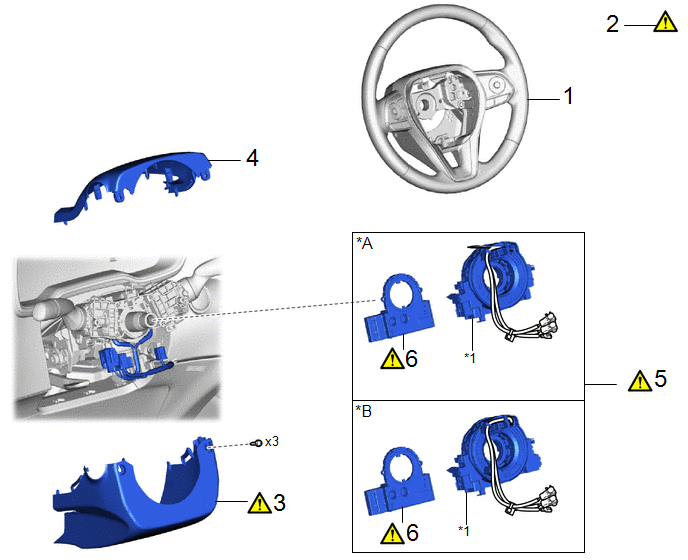
|
Procedure | Part Name Code |
.png) |
.png) |
 |
|---|---|---|---|---|---|
|
1 | STEERING WHEEL ASSEMBLY |
45100 | - |
- | - |
|
2 | ALIGN FRONT WHEELS FACING STRAIGHT AHEAD |
- |
|
- | - |
|
3 | LOWER STEERING COLUMN COVER |
45287 |
|
- | - |
|
4 | UPPER STEERING COLUMN COVER |
45286B | - |
- | - |
|
5 | SPIRAL CABLE WITH SENSOR SUB-ASSEMBLY |
- |
|
- | - |
|
6 | STEERING SENSOR |
89245B |
|
- | - |
|
*1 | SPIRAL CABLE SUB-ASSEMBLY |
- | - |
CAUTION / NOTICE / HINT
The necessary procedures (adjustment, calibration, initialization, or registration) that must be performed after parts are removed and installed, or replaced during the steering sensor removal/installation are shown below.
Necessary Procedures After Parts Removed/Installed/Replaced|
Replacement Part or Procedure |
Necessary Procedures | Effect/Inoperative Function When Necessary Procedures are not Performed |
Link |
|---|---|---|---|
| *: When the steering sensor is replaced with a new one, ECU security key is necessary. | |||
| Steering sensor |
Update ECU security key* |
Vehicle control history (RoB) are stored |
|
NOTICE:
After the ignition switch is turned off, the radio and display receiver assembly records various types of memory and settings. As a result, after turning the ignition switch off, make sure to wait at least 120 seconds before disconnecting the cable from the negative (-) auxiliary battery terminal.
HINT:
When the cable is disconnected/reconnected to the auxiliary battery terminal, systems temporarily stop operating. However, each system has a function that completes learning the first time the system is used.
- Learning completes when vehicle is driven
Effect/Inoperative Function When Necessary Procedures are not Performed
Necessary Procedures
Link
*A: for Gasoline Model Front Camera System
Drive the vehicle straight ahead at 15 km/h (10 mph) or more for 1 second or more.
.gif)
Stop and start system*A
Drive the vehicle until stop and start control is permitted (approximately 5 to 60 minutes)
- Learning completes when vehicle is operated normally
Effect/Inoperative Function When Necessary Procedures are not Performed
Necessary Procedures
Link
Power door lock control system
- Back door opener
Perform door unlock operation with door control switch or electrical key transmitter sub-assembly switch.
Power back door system
Fully close the back door by hand.
HINT:
Initialization is not necessary if the above procedures are performed while the back door is closed.
Air conditioning system
After the ignition switch is turned to ON, the servo motor standard position is recognized.
-
PROCEDURE
1. REMOVE STEERING WHEEL ASSEMBLY
Click here
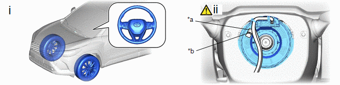
2. ALIGN FRONT WHEELS FACING STRAIGHT AHEAD
|
*a | Check Window |
*b | Top of Flat Cable U-turn |
(1) Check that the front wheels are facing straight ahead.
(2) Check that the spiral cable with sensor sub-assembly is center position.
OK:
The connector is at the top.
The colored roller or the top of the flat cable U-turn can be checked from the check window.
NOTICE:
If the result is not as specified, it is possible that the spiral cable sub-assembly is broken. Replace the spiral cable sub-assembly with a new one.
3. REMOVE LOWER STEERING COLUMN COVER
|
|
Click here |
4. REMOVE UPPER STEERING COLUMN COVER
Click here
5. REMOVE SPIRAL CABLE WITH SENSOR SUB-ASSEMBLY
|
|
NOTICE:
|
.png)
|
*A | w/ Smart Key System |
*B | w/o Smart Key System |
|
*a | Illumination off |
- | - |
(1) Check that the ignition switch is off.
(2) Check that the cable is disconnected from the negative (-) auxiliary battery terminal.
CAUTION:
- Wait at least 90 seconds after disconnecting the cable from the negative (-) auxiliary battery terminal to disable the SRS system.
- If the airbag deploys for any reason, it may cause a serious accident.
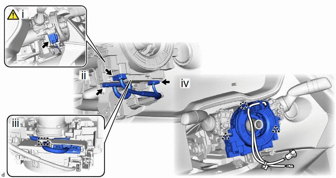
(1) Disconnect the airbag connector.
NOTICE:
When disconnecting any airbag connector, take care not to damage the airbag wire harness.
HINT:
Refer to How to Connect or Disconnect Airbag Connector:
Click here
(2) Disconnect each connector.
(3) Separate the wire harness from the spiral cable with sensor sub-assembly.
(4) Disengage the claw and clips to remove the spiral cable with sensor sub-assembly.
6. REMOVE STEERING SENSOR
|
|
NOTICE: Remove the steering sensor from the spiral cable sub-assembly only when replacing the spiral cable sub-assembly. |
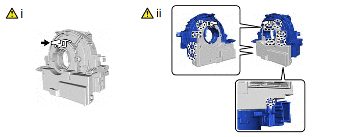
(1) Install the lock pin to the steering sensor.
NOTICE:
- Use the lock pin provided with a new spiral cable sub-assembly.
- Do not remove the lock pin before installing the steering sensor to the spiral cable sub-assembly.
(2) Disengage the claws and pins to remove the spiral cable sub-assembly from the steering sensor.
NOTICE:
Do not damage the pins of the spiral cable sub-assembly or guides of the steering sensor.


