Toyota Corolla Cross: Removal
REMOVAL
CAUTION / NOTICE / HINT
COMPONENTS (REMOVAL)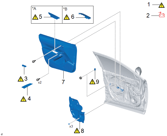
|
Procedure | Part Name Code |
.png) |
.png) |
 |
|---|---|---|---|---|---|
|
1 | PRECAUTION |
- |
|
- | - |
|
2 | CABLE FROM NEGATIVE AUXILIARY BATTERY TERMINAL |
- |
|
- | - |
|
3 | FRONT DOOR INSIDE HANDLE BEZEL PLUG |
69284F |
|
- | - |
|
4 | DOOR ASSIST GRIP COVER |
74646 |
|
- | - |
|
5 | MULTIPLEX NETWORK MASTER SWITCH ASSEMBLY WITH FRONT DOOR UPPER ARMREST BASE PANEL |
- |
|
- | - |
|
6 | POWER WINDOW REGULATOR SWITCH ASSEMBLY WITH FRONT DOOR UPPER ARMREST BASE PANEL |
- |
|
- | - |
|
7 | FRONT DOOR TRIM BOARD SUB-ASSEMBLY |
67602 | - |
- | - |
|
8 | FRONT DOOR SERVICE HOLE COVER |
67832 |
|
- | - |
|
9 | SIDE AIRBAG PRESSURE SENSOR |
8983AA |
|
- | - |
|
*A | for Driver Side |
*B | for Front Passenger Side |
CAUTION / NOTICE / HINT
The necessary procedures (adjustment, calibration, initialization, or registration) that must be performed after parts are removed and installed, or replaced during the horn button assembly removal/installation are shown below.
NOTICE:
After the ignition switch is turned off, the radio and display receiver assembly records various types of memory and settings. As a result, after turning the ignition switch off, make sure to wait at least 120 seconds before disconnecting the cable from the negative (-) auxiliary battery terminal.
HINT:
When the cable is disconnected/reconnected to the auxiliary battery terminal, systems temporarily stop operating. However, each system has a function that completes learning the first time the system is used.
- Learning completes when vehicle is driven
Effect/Inoperative Function When Necessary Procedures are not Performed
Necessary Procedures
Link
*A: for Gasoline Model Front Camera System
Drive the vehicle straight ahead at 15 km/h (10 mph) or more for 1 second or more.
.gif)
Stop and start system*A
Drive the vehicle until stop and start control is permitted (approximately 5 to 60 minutes)
- Learning completes when vehicle is operated normally
Effect/Inoperative Function When Necessary Procedures are not Performed
Necessary Procedures
Link
Power door lock control system
- Back door opener
Perform door unlock operation with door control switch or electrical key transmitter sub-assembly switch.
Power back door system
Fully close the back door by hand.
HINT:
Initialization is not necessary if the above procedures are performed while the back door is closed.
Air conditioning system
After the ignition switch is turned to ON, the servo motor standard position is recognized.
-
PROCEDURE
1. PRECAUTION
|
|
CAUTION: Be sure to read Precaution thoroughly before servicing. .png) Click here
NOTICE: After turning the ignition switch off, waiting time may be required before disconnecting the cable from the negative (-) auxiliary battery terminal. Click here |
2. DISCONNECT CABLE FROM NEGATIVE AUXILIARY BATTERY TERMINAL
|
|
.png)
|
- for Gasoline Model
Click here
- for HEV Model
Click here
3. REMOVE FRONT DOOR INSIDE HANDLE BEZEL PLUG
|
|
Click here |
4. REMOVE DOOR ASSIST GRIP COVER
|
|
Click here |
5. REMOVE MULTIPLEX NETWORK MASTER SWITCH ASSEMBLY WITH FRONT DOOR UPPER ARMREST BASE PANEL (for Driver Side)
|
|
Click here |
6. REMOVE POWER WINDOW REGULATOR SWITCH ASSEMBLY WITH FRONT DOOR UPPER ARMREST BASE PANEL (for Front Passenger Side)
|
|
Click here |
7. REMOVE FRONT DOOR TRIM BOARD SUB-ASSEMBLY
Click here
8. REMOVE FRONT DOOR SERVICE HOLE COVER
|
|
Click here |
9. REMOVE SIDE AIRBAG PRESSURE SENSOR
.png)
|
*A | w/ Smart Key System |
*B | w/o Smart Key System |
|
*a | Illumination off |
- | - |
(1) Check that the ignition switch is off.
(2) Check that the cable is disconnected from the negative (-) auxiliary battery terminal.
CAUTION:
- Wait at least 90 seconds after disconnecting the cable from the negative (-) auxiliary battery terminal to disable the SRS system.
- If the airbag deploys for any reason, it may cause a serious accident.
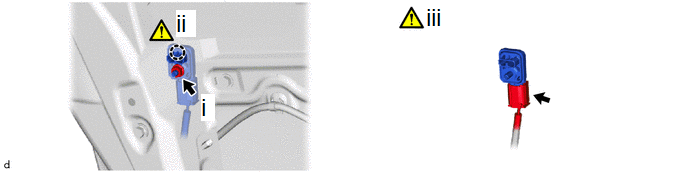
(1) Remove the nut.
NOTICE:
Do not reuse the nut.
(2) Disengage the claw to pull out the side airbag pressure sensor.
NOTICE:
If the side airbag pressure sensor has been dropped, replace it with a new one.
(3) Disconnect the airbag connector.
NOTICE:
When disconnecting any airbag connector, take care not to damage the airbag wire harness.
HINT:
Refer to How to Connect or Disconnect Airbag Connector:
Click here


