Toyota Corolla Cross: Removal
REMOVAL
CAUTION / NOTICE / HINT
COMPONENTS (REMOVAL)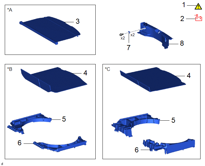
|
Procedure | Part Name Code |
.png) |
.png) |
 |
|---|---|---|---|---|---|
|
1 | PRECAUTION |
- |
|
- | - |
|
2 | DISCONNECT CABLE FROM NEGATIVE AUXILIARY BATTERY TERMINAL |
- | - |
- | - |
|
3 | TONNEAU COVER ASSEMBLY |
64910J | - |
- | - |
|
4 | DECK BOARD ASSEMBLY |
58410B | - |
- | - |
|
5 | DECK FLOOR BOX RH |
64995 | - |
- | - |
|
6 | DECK FLOOR BOX LH |
64997 | - |
- | - |
|
7 | LUGGAGE HOLD BELT STRIKER ASSEMBLY |
58460D | - |
- | - |
|
8 | REAR DECK TRIM COVER |
64716D | - |
- | - |
|
*A | w/ Tonneau Cover |
*B | for Full Size Spare Tire |
|
*C | for Compact Spare Tire |
- | - |
|
Procedure | Part Name Code |
|
|
| |
|---|---|---|---|---|---|
|
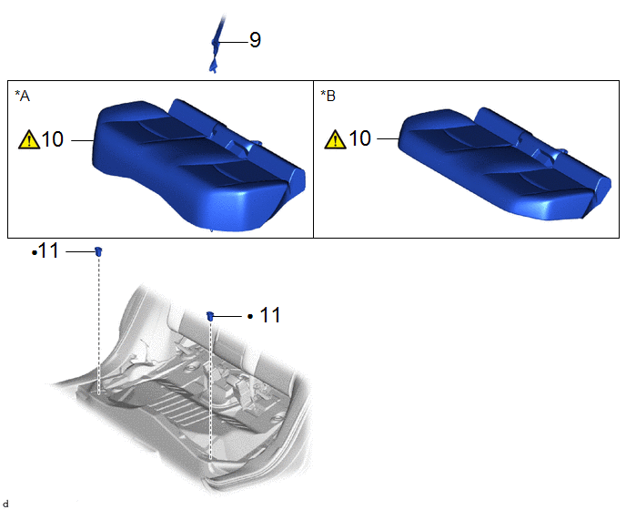
9 | REAR CENTER SEAT OUTER BELT ASSEMBLY |
73350C | - |
- | - |
|
10 | BENCH TYPE REAR SEAT CUSHION ASSEMBLY |
- |
|
- | - |
|
11 | REAR SEAT CUSHION LOCK HOOK |
72693 | - |
- | - |
|
*A | for Gasoline Model |
*B | for HEV Model |
|
● | Non-reusable part |
- | - |
|
Procedure | Part Name Code |
|
|
| |
|---|---|---|---|---|---|
|
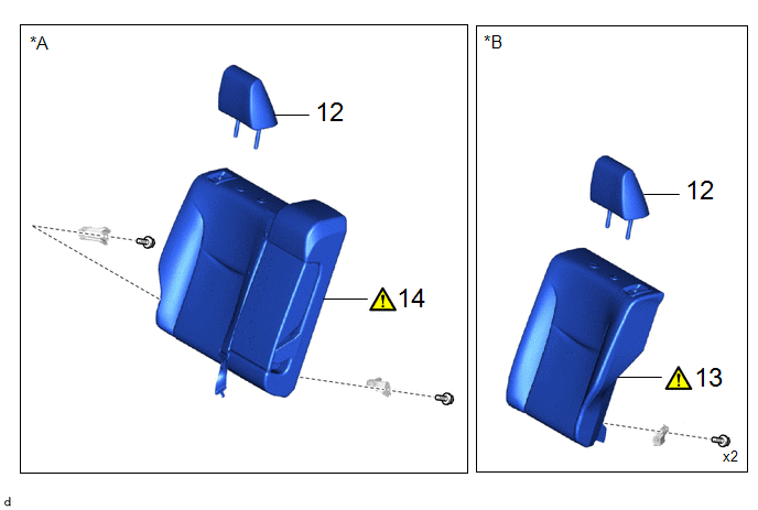
12 | REAR SEAT HEADREST ASSEMBLY |
71940A | - |
- | - |
|
13 | REAR SEATBACK ASSEMBLY LH |
- |
|
- | - |
|
14 | REAR SEATBACK ASSEMBLY RH |
- |
|
- | - |
|
*A | for RH Side |
*B | for LH Side |
|
Procedure | Part Name Code |
|
|
| |
|---|---|---|---|---|---|
|
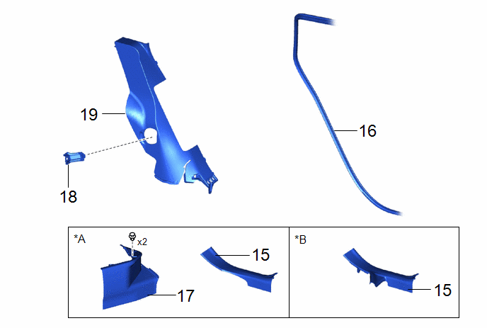
15 | REAR DOOR SCUFF PLATE |
67918A | - |
- | - |
|
16 | REAR DOOR OPENING TRIM WEATHERSTRIP |
62332A | - |
- | - |
|
17 | REAR UNDER SIDE COVER |
76974F | - |
- | - |
|
18 | REAR SEATBACK HINGE SUB-ASSEMBLY |
71304C | - |
- | - |
|
19 | REAR SEAT SIDE GARNISH |
62552F | - |
- | - |
|
*A | for Gasoline Model |
*B | for HEV Model |
|
Procedure | Part Name Code |
|
|
| |
|---|---|---|---|---|---|
|
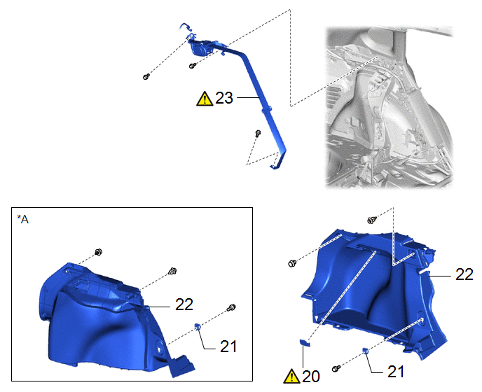
20 | NO. 1 LUGGAGE COMPARTMENT LIGHT ASSEMBLY |
81330 |
|
- | - |
|
21 | LUGGAGE HOLD BELT STRIKER ASSEMBLY |
58460D | - |
- | - |
|
22 | DECK TRIM SIDE PANEL ASSEMBLY |
64740C | - |
- | - |
|
23 | REAR SEAT OUTER BELT ASSEMBLY |
73370E |
|
- | - |
|
*A | for RH Side |
- | - |
CAUTION / NOTICE / HINT
The necessary procedures (adjustment, calibration, initialization, or registration) that must be performed after parts are removed and installed, or replaced during the rear seat outer belt assembly removal/installation are shown below.
HINT:
- When the cable is disconnected / reconnected to the auxiliary battery terminal, systems temporarily stop operating. However, each system has a function that completes learning the first time the system is used.
- Learning completes when vehicle is driven
Effect / Inoperative Function When Necessary Procedures are not Performed
Necessary Procedures
Link
*A: for Gasoline Model Front Camera System
Drivre the vehicle straight ahead at 15 km/h (10mph) or more for 1 second or more.
.gif)
Stop and start system *A
Drive the vehicle until stop and start control ispermitted (appoximately 5 to 60 minutes)
- Learning completes when vehicle is operated normally
Effect / Inoperative Function When Necessary Procedures are not Performed
Necessary Procedures
Link
Power door lock control system
- Back door opener
Perform door unlock operation with door control switch or electrical key transmitter sub-assembly switch.
Power back door system
Fully close the back door by hand.
HINT:
Initialization is not necessary if the above procedures are performed while the back door is closed.
Air conditioning system
After the ignition switch is turned to ON, the servo motor standard position is recognized.
-
- Learning completes when vehicle is driven
- Use the same procedure for the RH side and LH side.
- The following procedure is for the LH side.
PROCEDURE
1. PRECAUTION
|
|
CAUTION: Some of these service operations affect the SRS airbag system. Read precautionary notices concerning the SRS airbag system before servicing. .png)
NOTICE: After the ignition switch is turned off, there may be a waiting time before disconnecting the negative (-) auxiliary battery terminal. |
2. DISCONNECT CABLE FROM NEGATIVE AUXILIARY BATTERY TERMINAL
|
|
CAUTION:
.png) |
Click here
3. REMOVE TONNEAU COVER ASSEMBLY (w/ Tonneau Cover)
Click here
4. REMOVE DECK BOARD ASSEMBLY
Click here
5. REMOVE DECK FLOOR BOX RH
Click here
6. REMOVE DECK FLOOR BOX LH
Click here
7. REMOVE LUGGAGE HOLD BELT STRIKER ASSEMBLY
Click here
8. REMOVE REAR DECK TRIM COVER
Click here
9. DISCONNECT REAR CENTER SEAT OUTER BELT ASSEMBLY
Click here
10. REMOVE BENCH TYPE REAR SEAT CUSHION ASSEMBLY
|
|
|
11. REMOVE REAR SEAT CUSHION LOCK HOOK
Click here
12. REMOVE REAR SEAT HEADREST ASSEMBLY
Click here
13. REMOVE REAR SEATBACK ASSEMBLY LH (for LH Side)
Click here
14. REMOVE REAR SEATBACK ASSEMBLY RH (for RH Side)
Click here
15. REMOVE REAR DOOR SCUFF PLATE
Click here
16. DISCONNECT REAR DOOR OPENING TRIM WEATHERSTRIP

17. REMOVE REAR UNDER SIDE COVER (for HEV Model)
Click here
18. REMOVE REAR SEATBACK HINGE SUB-ASSEMBLY
Click here
19. REMOVE REAR SEAT SIDE GARNISH
Click here
20. REMOVE NO. 1 LUGGAGE COMPARTMENT LIGHT ASSEMBLY (for LH Side)
Click here
21. REMOVE LUGGAGE HOLD BELT STRIKER ASSEMBLY
Click here
22. REMOVE DECK TRIM SIDE PANEL ASSEMBLY
Click here
23. REMOVE REAR SEAT OUTER BELT ASSEMBLY
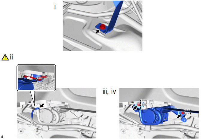
(1) Remove the bolt to disconnect the floor anchor of the rear seat outer belt assembly.
(2) Disconnect the pretensioner connector.
HINT:
Refer to How to Connector or Disconnect Airbag Connector:
Click here
(3) Remove the 2 bolts.
(4) Disengage the 3 guides to remove the rear seat outer belt assembly.


