Toyota Corolla Cross: Removal
REMOVAL
CAUTION / NOTICE / HINT
COMPONENTS (REMOVAL)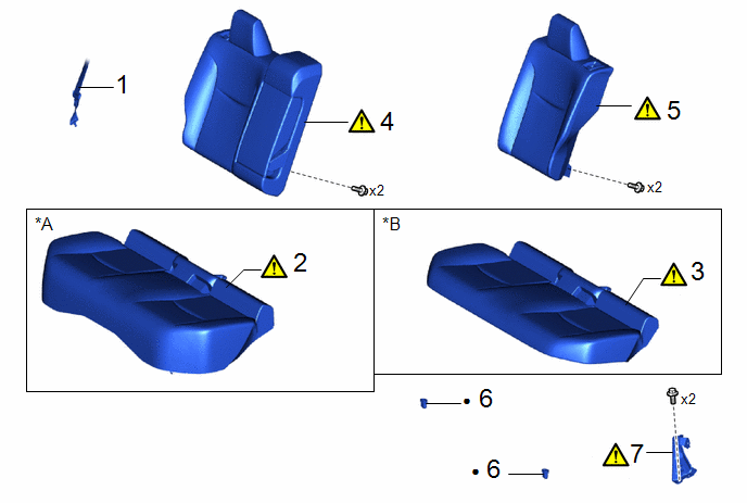
|
Procedure | Part Name Code |
.png) |
.png) |
 |
|---|---|---|---|---|---|
|
1 | REAR CENTER SEAT OUTER BELT ASSEMBLY |
73350C | - |
- | - |
|
2 | BENCH TYPE REAR SEAT CUSHION ASSEMBLY |
- |
|
- | - |
|
3 | BENCH TYPE REAR SEAT CUSHION ASSEMBLY |
- |
|
- | - |
|
4 | REAR SEATBACK ASSEMBLY RH |
- |
|
- | - |
|
5 | REAR SEATBACK ASSEMBLY LH |
- |
|
- | - |
|
6 | REAR SEAT CUSHION LOCK HOOK |
72693 | - |
- | - |
|
7 | REAR CENTER SEATBACK HINGE SUB-ASSEMBLY |
71305A |
|
- | - |
|
*A | for Gasoline Model |
*B | for HEV Model |
|
● | Non-reusable part |
- | - |
CAUTION / NOTICE / HINT
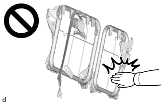
CAUTION:
Wear protective gloves. Sharp areas on the parts may injure your hands.
PROCEDURE
1. DISCONNECT REAR CENTER SEAT OUTER BELT ASSEMBLY

2. REMOVE BENCH TYPE REAR SEAT CUSHION ASSEMBLY (for Gasoline Model)
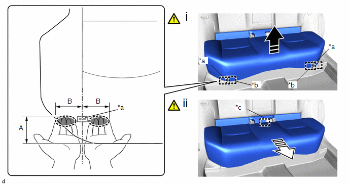
|
*a | Rear Seat Cushion Frame Hook Front Side |
*b | Guide |
|
*c | Rear Seat Cushion Frame Hook Rear Side |
- | - |
.png) |
Place Hand Here |
.png) |
Remove in this Direction (1) |
.png) |
Remove in this Direction (2) |
- | - |
(1) Lift the front edge of the bench type rear seat cushion assembly as shown in the illustration and disengage the rear seat cushion frame hooks on the front side and guides of the bench type rear seat cushion assembly from the rear seat cushion lock hooks.
NOTICE:
Be sure to hold the parts of the seat cushion assembly directly next to the rear seat cushion frame hooks when lifting it. Lifting a different part of the cushion may deform the rear seat cushion frame.
Standard Measurement:
|
Area | Measurement |
Area | Measurement |
|---|---|---|---|
|
A | 60 mm (2.36 in.) |
B | 80 mm (3.15 in.) |
(2) Disengage the rear seat cushion frame hook on the rear side of the bench type rear seat cushion assembly as shown in the illustration.
NOTICE:
Be careful not to damage the bench type rear seat cushion assembly, body exterior or interior parts.
3. REMOVE BENCH TYPE REAR SEAT CUSHION ASSEMBLY (for HEV Model)
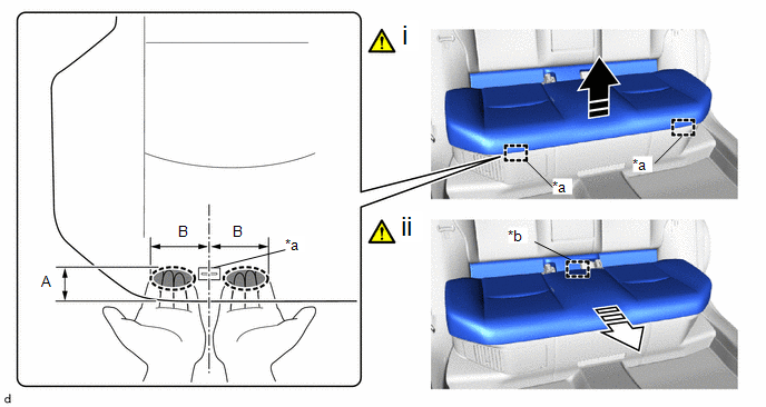
|
*a | Rear Seat Cushion Frame Hook Front Side |
*b | Rear Seat Cushion Frame Hook Rear Side |
.png) |
Place Hand Here |
.png) |
Remove in this Direction (1) |
.png) |
Remove in this Direction (2) |
- | - |
(1) Lift the front edge of the bench type rear seat cushion assembly as shown in the illustration and disengage the rear seat cushion frame hooks on the front side of the bench type rear seat cushion assembly from the rear seat cushion lock hooks.
NOTICE:
Be sure to hold the parts of the seat cushion assembly directly next to the rear seat cushion frame hooks when lifting it. Lifting a different part of the cushion may deform the rear seat cushion frame.
Standard Measurement:
|
Area | Measurement |
Area | Measurement |
|---|---|---|---|
|
A | 60 mm (2.36 in.) |
B | 80 mm (3.15 in.) |
(2) Disengage the rear seat cushion frame hook on the rear side of the bench type rear seat cushion assembly as shown in the illustration.
NOTICE:
Be careful not to damage the bench type rear seat cushion assembly, body exterior or interior parts.
4. REMOVE REAR SEATBACK ASSEMBLY RH
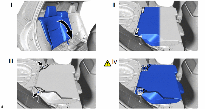
(1) Fold the rear seatback assembly RH forward.
(2) Disengage the hook and loop fasteners.
(3) Remove the 2 bolts.
(4) Disengage the guides to remove the rear seatback assembly RH.
NOTICE:
Be careful not to damage the vehicle body.
5. REMOVE REAR SEATBACK ASSEMBLY LH
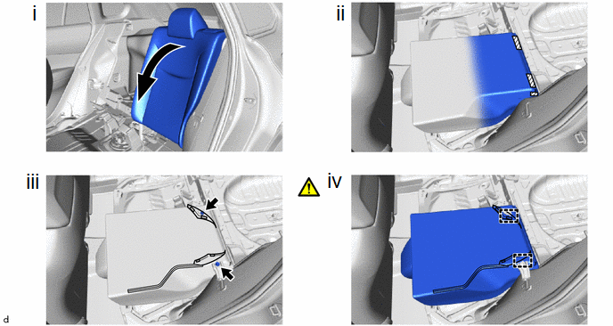
(1) Fold the rear seatback assembly LH forward.
(2) Disengage the hook and loop fasteners.
(3) Remove the 2 bolts.
(4) Disengage the guides to remove the rear seatback assembly LH.
NOTICE:
Be careful not to damage the vehicle body.
6. REMOVE REAR SEAT CUSHION LOCK HOOK

7. REMOVE REAR CENTER SEATBACK HINGE SUB-ASSEMBLY
.png) |
HINT: Perform this procedure only when replacement of the rear center seatback hinge sub-assembly is necessary. |


.gif)

