Toyota Corolla Cross: Removal
REMOVAL
CAUTION / NOTICE / HINT
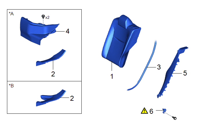
COMPONENTS (REMOVAL)
|
Procedure | Part Name Code |
.png) |
.png) |
 |
|---|---|---|---|---|---|
|
1 | REAR SEAT ASSEMBLY |
- | - |
- | - |
|
2 | REAR DOOR SCUFF PLATE |
67918A | - |
- | - |
|
3 | REAR DOOR OPENING TRIM WEATHERSTRIP |
62332A | - |
- | - |
|
4 | REAR UNDER SIDE COVER |
76974E | - |
- | - |
|
5 | REAR SEAT SIDE GARNISH |
62552F | - |
- | - |
|
6 | REAR DOOR COURTESY LIGHT SWITCH ASSEMBLY |
84234 |
|
- | - |
|
*A | for HEV Model |
*B | for Gasoline Model |
CAUTION / NOTICE / HINT
HINT:
- Use the same procedure for the RH side and LH side.
- The following procedure is for the LH side.
PROCEDURE
1. REMOVE REAR SEAT ASSEMBLY
Click here
.gif)
2. REMOVE REAR DOOR SCUFF PLATE
Click here
.gif)
3. DISCONNECT REAR DOOR OPENING TRIM WEATHERSTRIP
Click here .gif)
4. REMOVE REAR UNDER SIDE COVER (for HEV Model)
Click here .gif)
5. REMOVE REAR SEAT SIDE GARNISH
Click here .gif)
6. REMOVE REAR DOOR COURTESY LIGHT SWITCH ASSEMBLY

(1) Disconnect the connector.
(2) Using a T30 "TORX" socket wrench, remove the bolt to remove the rear door courtesy light switch assembly.


