Toyota Corolla Cross: Removal
REMOVAL
CAUTION / NOTICE / HINT
COMPONENTS (REMOVAL)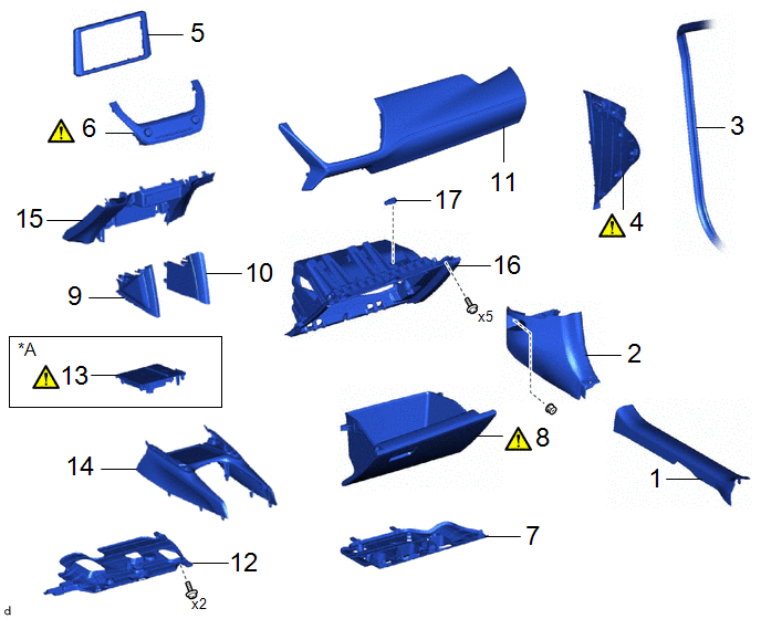
|
Procedure | Part Name Code |
.png) |
.png) |
 |
|---|---|---|---|---|---|
|
1 | FRONT DOOR SCUFF PLATE RH |
67913 | - |
- | - |
|
2 | COWL SIDE TRIM SUB-ASSEMBLY RH |
62111C | - |
- | - |
|
3 | FRONT DOOR OPENING TRIM WEATHERSTRIP RH |
62311B | - |
- | - |
|
4 | NO. 2 INSTRUMENT SIDE PANEL |
55318F |
|
- | - |
|
5 | CENTER INSTRUMENT CLUSTER FINISH PANEL SUB-ASSEMBLY |
55405B | - |
- | - |
|
6 | AIR CONDITIONING CONTROL ASSEMBLY |
55900 |
|
- | - |
|
7 | NO. 2 INSTRUMENT PANEL UNDER COVER SUB-ASSEMBLY |
55607 | - |
- | - |
|
8 | GLOVE COMPARTMENT DOOR ASSEMBLY |
55550 |
|
- | - |
|
9 | NO. 2 CONSOLE UPPER PANEL GARNISH |
58834B | - |
- | - |
|
10 | NO. 1 CONSOLE UPPER PANEL GARNISH |
58833B | - |
- | - |
|
11 | INSTRUMENT CLUSTER FINISH PANEL GARNISH ASSEMBLY |
55470 | - |
- | - |
|
12 | NO. 1 INSTRUMENT PANEL UNDER COVER SUB-ASSEMBLY |
55606 | - |
- | - |
|
13 | MOBILE WIRELESS CHARGER CRADLE ASSEMBLY |
861C0 |
|
- | - |
|
14 | FRONT CONSOLE UPPER PANEL GARNISH |
58831A | - |
- | - |
|
15 | LOWER CENTER INSTRUMENT PANEL FINISH PANEL |
55434F | - |
- | - |
|
16 | LOWER NO. 2 INSTRUMENT PANEL FINISH PANEL |
55433B | - |
- | - |
|
17 | GLOVE BOX LIGHT ASSEMBLY |
81260 | - |
- | - |
|
*A | w/ Wireless Charger |
- | - |
PROCEDURE
1. REMOVE FRONT DOOR SCUFF PLATE RH
(a) Use the same procedure as for the LH side.
Click here .gif)
2. REMOVE COWL SIDE TRIM SUB-ASSEMBLY RH
(a) Use the same procedure as for the LH side.
Click here
3. DISCONNECT FRONT DOOR OPENING TRIM WEATHERSTRIP RH
(a) Use the same procedure as for the LH side.
Click here
4. REMOVE NO. 2 INSTRUMENT SIDE PANEL
|
|
|
5. REMOVE CENTER INSTRUMENT CLUSTER FINISH PANEL SUB-ASSEMBLY
Click here
6. REMOVE AIR CONDITIONING CONTROL ASSEMBLY
|
|
Click here |
7. REMOVE NO. 2 INSTRUMENT PANEL UNDER COVER SUB-ASSEMBLY
Click here
8. REMOVE GLOVE COMPARTMENT DOOR ASSEMBLY
|
|
Click here |
9. REMOVE NO. 2 CONSOLE UPPER PANEL GARNISH
Click here
10. REMOVE NO. 1 CONSOLE UPPER PANEL GARNISH
(a) Use the same procedure as for the No. 2 console upper panel garnish.
11. REMOVE INSTRUMENT CLUSTER FINISH PANEL GARNISH ASSEMBLY
Click here
12. REMOVE NO. 1 INSTRUMENT PANEL UNDER COVER SUB-ASSEMBLY
Click here
13. REMOVE MOBILE WIRELESS CHARGER CRADLE ASSEMBLY (w/ Wireless Charger)
|
|
Click here |
14. REMOVE FRONT CONSOLE UPPER PANEL GARNISH
Click here
15. REMOVE LOWER CENTER INSTRUMENT PANEL FINISH PANEL
Click here
16. REMOVE LOWER NO. 2 INSTRUMENT PANEL FINISH PANEL
Click here
17. REMOVE GLOVE BOX LIGHT ASSEMBLY

.png) |
Remove in this Direction |
- | - |


