Toyota Corolla Cross: Removal
REMOVAL
CAUTION / NOTICE / HINT
COMPONENTS (REMOVAL)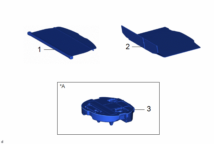
|
Procedure | Part Name Code |
.png) |
.png) |
 |
|---|---|---|---|---|---|
|
1 | TONNEAU COVER ASSEMBLY |
64910J | - |
- | - |
|
2 | DECK BOARD ASSEMBLY |
58410B | - |
- | - |
|
3 | SPARE WHEEL CUSHION |
64777J | - |
- | - |
|
*A | w/o Spare Tire |
- | - |
|
Procedure | Part Name Code |
|
|
| |
|---|---|---|---|---|---|
|
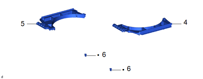
4 | DECK FLOOR BOX LH |
64997 | - |
- | - |
|
5 | DECK FLOOR BOX RH |
64995 | - |
- | - |
|
6 | REAR SEAT CUSHION LOCK HOOK |
72693 | - |
- | - |
|
● | Non-reusable part |
- | - |
|
Procedure | Part Name Code |
|
|
| |
|---|---|---|---|---|---|
|
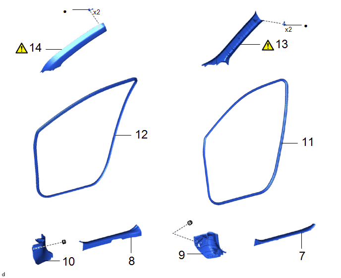
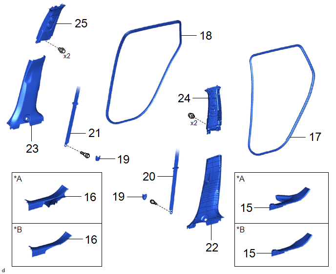
7 | FRONT DOOR SCUFF PLATE LH |
67914B | - |
- | - |
|
8 | FRONT DOOR SCUFF PLATE RH |
67913 | - |
- | - |
|
9 | COWL SIDE TRIM SUB-ASSEMBLY LH |
62112A | - |
- | - |
|
10 | COWL SIDE TRIM SUB-ASSEMBLY RH |
62111 | - |
- | - |
|
11 | FRONT DOOR OPENING TRIM WEATHERSTRIP LH |
62312B | - |
- | - |
|
12 | FRONT DOOR OPENING TRIM WEATHERSTRIP RH |
62311B | - |
- | - |
|
13 | FRONT PILLAR GARNISH ASSEMBLY LH |
62212B |
|
- | - |
|
14 | FRONT PILLAR GARNISH ASSEMBLY RH |
62211U |
|
- | - |
|
● | Non-reusable part |
- | - |
|
Procedure | Part Name Code |
|
|
| |
|---|---|---|---|---|---|
|
15 | REAR DOOR SCUFF PLATE LH |
67918A | - |
- | - |
|
16 | REAR DOOR SCUFF PLATE RH |
67917A | - |
- | - |
|
17 | REAR DOOR OPENING TRIM WEATHERSTRIP LH |
62332A | - |
- | - |
|
18 | REAR DOOR OPENING TRIM WEATHERSTRIP RH |
62331A | - |
- | - |
|
19 | LAP BELT OUTER ANCHOR COVER |
73233 | - |
- | - |
|
20 | FRONT SEAT OUTER BELT ASSEMBLY LH |
73220 | - |
- | - |
|
21 | FRONT SEAT OUTER BELT ASSEMBLY RH |
73210 | - |
- | - |
|
22 | CENTER PILLAR LOWER GARNISH LH |
62414A | - |
- | - |
|
23 | CENTER PILLAR LOWER GARNISH RH |
62413A | - |
- | - |
|
24 | CENTER PILLER UPPER GARNISH LH |
62420A | - |
- | - |
|
25 | CENTER PILLAR UPPER GARNISH RH |
62410A | - |
- | - |
|
*A | for Gasoline Model |
*B | for HEV Model |
|
Procedure | Part Name Code |
|
|
| |
|---|---|---|---|---|---|
|
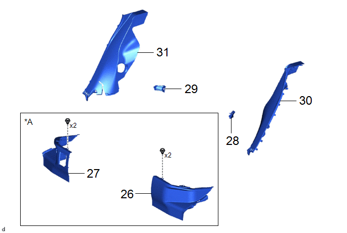
26 | REAR UNDER SIDE COVER LH |
76974E | - |
- | - |
|
27 | REAR UNDER SIDE COVER RH |
76973E | - |
- | - |
|
28 | REAR SEAT BACK HINGE SUB-ASSEMBLY LH |
71304C | - |
- | - |
|
29 | REAR SEAT BACK HINGE SUB-ASSEMBLY RH |
71303C | - |
- | - |
|
30 | REAR SEAT SIDE GARNISH LH |
62552F | - |
- | - |
|
31 | REAR SEAT SIDE GARNISH RH |
62551F | - |
- | - |
|
*A | for HEV Model |
- | - |
|
Procedure | Part Name Code |
|
|
| |
|---|---|---|---|---|---|
|
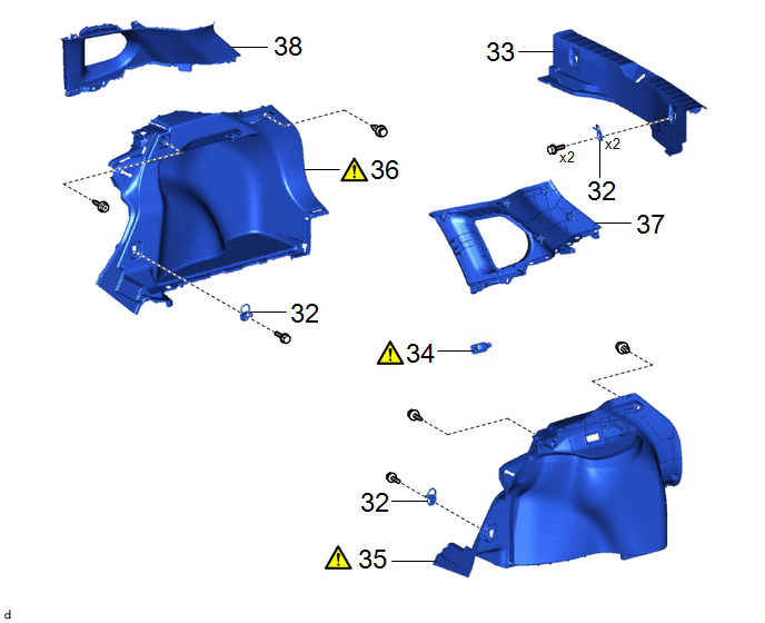
32 | LUGGAGE HOLD BELT STRIKER ASSEMBLY |
58460D | - |
- | - |
|
33 | REAR DECK TRIM COVER |
64716D | - |
- | - |
|
34 | NO. 1 LUGGAGE COMPARTMENT LIGHT ASSEMBLY |
81330 |
|
- | - |
|
35 | DECK TRIM SIDE PANEL ASSEMBLY LH |
64740C |
|
- | - |
|
36 | DECK TRIM SIDE PANEL ASSEMBLY RH |
64730B |
|
- | - |
|
37 | ROOF SIDE INNER GARNISH ASSEMBLY LH |
62480A | - |
- | - |
|
38 | ROOF SIDE INNER GARNISH ASSEMBLY RH |
62470A | - |
- | - |
|
Procedure | Part Name Code |
|
|
| |
|---|---|---|---|---|---|
|
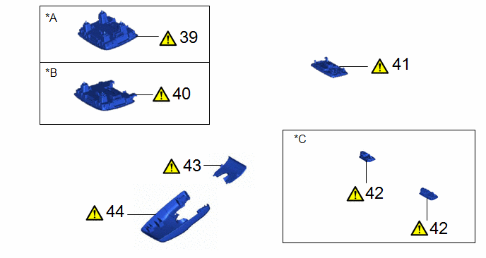
39 | MAP LIGHT ASSEMBLY |
81260A |
|
- | - |
|
40 | MAP LIGHT ASSEMBLY |
81260A |
|
- | - |
|
41 | NO. 1 ROOM LIGHT ASSEMBLY |
81240 |
|
- | - |
|
42 | VANITY LIGHT ASSEMBLY |
81340 |
|
- | - |
|
43 | NO. 2 FORWARD RECOGNITION COVER |
86466E |
|
- | - |
|
44 | NO. 1 FORWARD RECOGNITION COVER |
86466D |
|
- | - |
|
*A | w/o Sliding Roof |
*B | w/ Sliding Roof |
|
*C | w/ Vanity Light |
- | - |
|
Procedure | Part Name Code |
|
|
| |
|---|---|---|---|---|---|
|
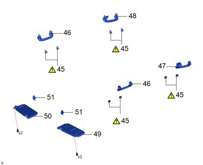
45 | ASSIST GRIP COVER |
74612 |
|
- | - |
|
46 | ASSIST GRIP SUB-ASSEMBLY |
74610A | - |
- | - |
|
47 | REAR ASSIST GRIP ASSEMBLY LH |
74630E | - |
- | - |
|
48 | REAR ASSIST GRIP ASSEMBLY RH |
74620C | - |
- | - |
|
49 | VISOR ASSEMBLY LH |
74320 | - |
- | - |
|
50 | VISOR ASSEMBLY RH |
74310 | - |
- | - |
|
51 | VISER HOLDER |
74348 | - |
- | - |
|
Procedure | Part Name Code |
|
|
| |
|---|---|---|---|---|---|
|
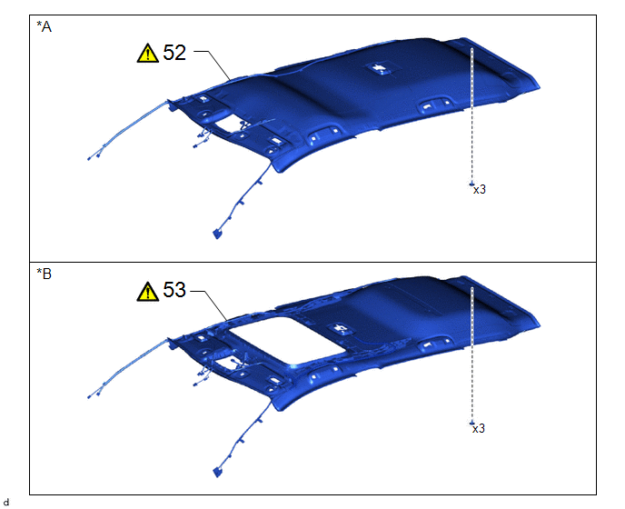
52 | ROOF HEADLINING ASSEMBLY |
63311C |
|
- | - |
|
53 | ROOF HEADLINING ASSEMBLY |
63311C |
|
- | - |
|
*A | w/o Sliding Roof |
*B | w/ Sliding Roof |
|
Procedure | Part Name Code |
|
|
| |
|---|---|---|---|---|---|
|
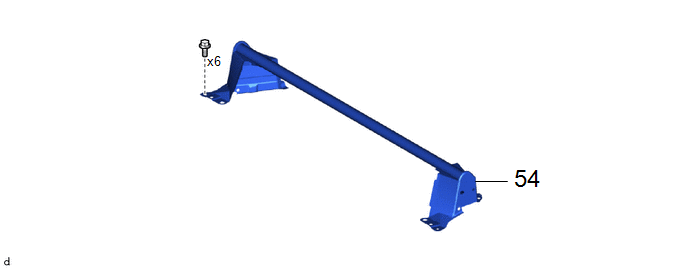
54 | CENTER FLOOR CROSSMEMBER GUSSET SUB-ASSEMBLY |
57047 | - |
- | - |
PROCEDURE
1. REMOVE TONNEAU COVER ASSEMBLY

2. REMOVE DECK BOARD ASSEMBLY

3. REMOVE SPARE WHEEL CUSHION (w/o Spare Tire)

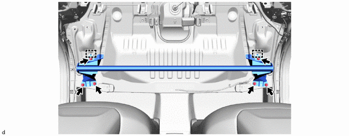
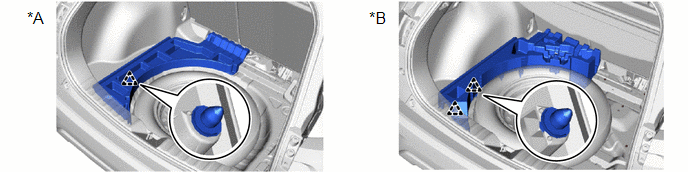
4. REMOVE DECK FLOOR BOX LH
|
*A | for 2WD |
*B | for AWD |
5. REMOVE DECK FLOOR BOX RH
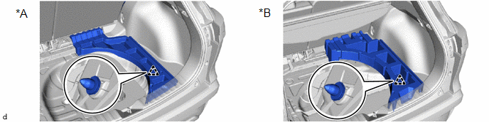
|
*A | for 2WD |
*B | for AWD |
6. REMOVE REAR SEAT CUSHION LOCK HOOK
Click here
.gif)
7. REMOVE FRONT DOOR SCUFF PLATE LH
 |
Place Hand Here |
.png) |
Remove in this Direction |
8. REMOVE FRONT DOOR SCUFF PLATE RH
(a) Use the same procedure as for the LH side.
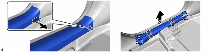
9. REMOVE COWL SIDE TRIM SUB-ASSEMBLY LH

|
|
Remove in this Direction |
- | - |
10. REMOVE COWL SIDE TRIM SUB-ASSEMBLY RH
(a) Use the same procedure as for the LH side.
11. REMOVE FRONT DOOR OPENING TRIM WEATHERSTRIP LH
Click here
12. REMOVE FRONT DOOR OPENING TRIM WEATHERSTRIP RH
(a) Use the same procedure as for the LH side.
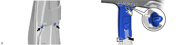
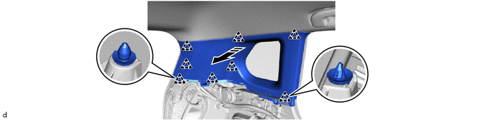
13. REMOVE FRONT PILLAR GARNISH ASSEMBLY LH
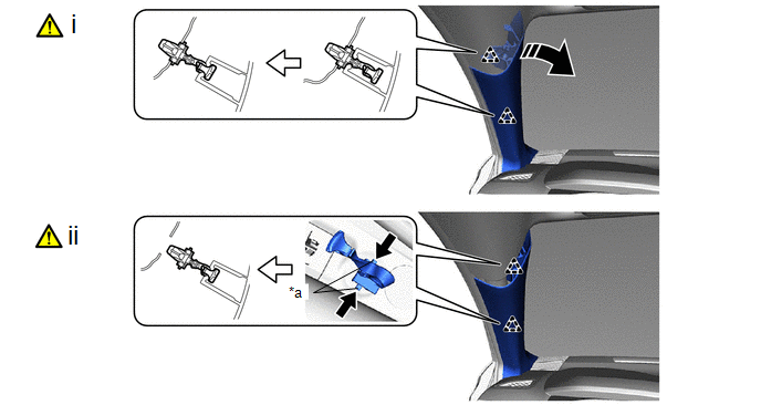
|
*a | Release Lever |
- | - |
.png) |
Push |
|
Pull up in this Direction |
(1) Pull up the front pillar garnish assembly LH to disengage the front pillar garnish clips as shown in the illustration.
(2) Push the release lever and separate the front pillar garnish clips from the vehicle body as shown in the illustration.
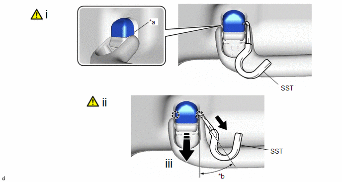
(b) When the front pillar garnish clip cannot be removed using your fingers:
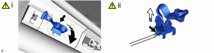
|
|
Lift in this Direction |
.png) |
Remove in this Direction |
(1) While pressing the part shown in the illustration with your finger, move the front pillar garnish clip in the direction indicated by the arrow shown in the illustration.
(2) While pulling the front pillar garnish clip in the direction indicated by the arrow, push the part shown in the illustration with the end of a screwdriver and remove the front pillar garnish clip.
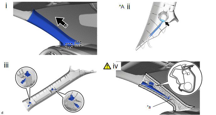
|
*A | w/ Speaker |
- | - |
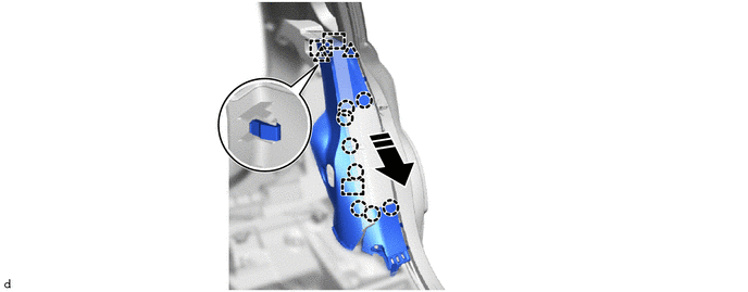
|
*a | Protective Cover |
- | - |
|
|
Remove in this Direction |
- | - |
(1) Disengage the guides to remove the front pillar garnish LH as shown in the illustration.
(2) w/ Speaker:
1. Disconnect the connector.
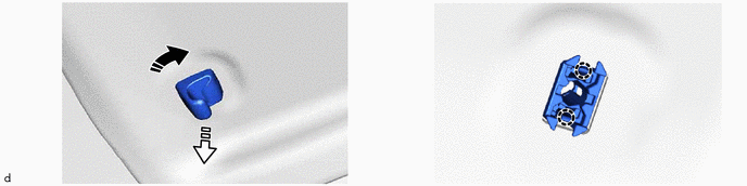
(3) Remove the 2 front pillar garnish clips from the front pillar garnish assembly LH.
(4) Completely cover the curtain shield airbag assembly LH with a cloth or nylon sheet and secure the ends of the cover with adhesive tape as shown in the illustration.
NOTICE:
Cover the curtain shield airbag assembly LH with a protective cover as soon as the front pillar garnish assembly LH is removed.
14. REMOVE FRONT PILLAR GARNISH ASSEMBLY RH
(a) Use the same procedure as for the LH side.
15. REMOVE REAR DOOR SCUFF PLATE LH
(a) for Gasoline Model:
|
|
Place Hand Here |
|
Remove in this Direction |
(b) for HEV Model:
|
|
Place Hand Here |
|
Remove in this Direction |
16. REMOVE REAR DOOR SCUFF PLATE RH
(a) Use the same procedure as for the LH side.
17. REMOVE REAR DOOR OPENING TRIM WEATHERSTRIP LH
Click here
18. REMOVE REAR DOOR OPENING TRIM WEATHERSTRIP RH
(a) Use the same procedure as for the LH side.
19. REMOVE LAP BELT OUTER ANCHOR COVER
Click here
20. DISCONNECT FRONT SEAT OUTER BELT ASSEMBLY LH
Click here
21. DISCONNECT FRONT SEAT OUTER BELT ASSEMBLY RH
(a) Use the same procedure as for the LH side.
22. REMOVE CENTER PILLAR LOWER GARNISH LH
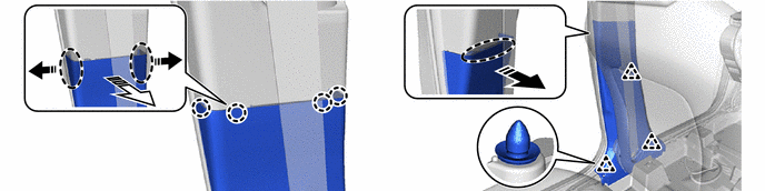
|
|
Place Hand Here |
|
Remove in this Direction (1) |
|
|
Remove in this Direction (2) |
- | - |
23. REMOVE CENTER PILLAR LOWER GARNISH RH
(a) Use the same procedure as for the LH side.
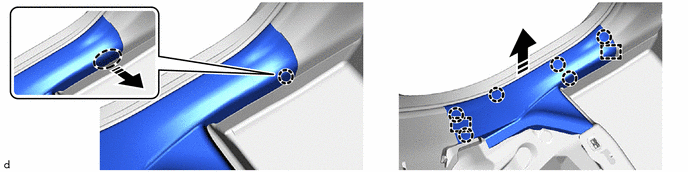
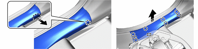
24. REMOVE CENTER PILLER UPPER GARNISH LH
|
|
Remove in this Direction (1) |
|
Remove in this Direction (2) |
25. REMOVE CENTER PILLAR UPPER GARNISH RH
(a) Use the same procedure as for the LH side.
26. REMOVE REAR UNDER SIDE COVER LH (for HEV Model)
Click here
27. REMOVE REAR UNDER SIDE COVER RH (for HEV Model)
(a) Use the same procedure as for the LH side.
28. REMOVE REAR SEAT BACK HINGE SUB-ASSEMBLY LH

29. REMOVE REAR SEAT BACK HINGE SUB-ASSEMBLY RH
(a) Use the same procedure as for the LH side.
30. REMOVE REAR SEAT SIDE GARNISH LH
|
|
Remove in this Direction |
- | - |
31. REMOVE REAR SEAT SIDE GARNISH RH
(a) Use the same procedure as for the LH side.
32. REMOVE LUGGAGE HOLD BELT STRIKER ASSEMBLY

(b) Use the same procedure for all of the luggage hold belt striker assembly.
33. REMOVE REAR DECK TRIM COVER
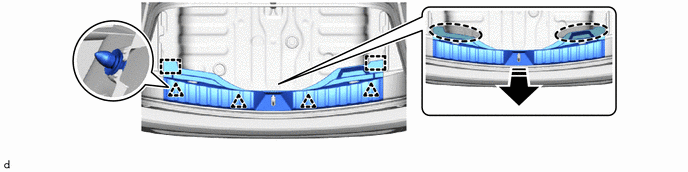
|
|
Place Hand Here |
|
Remove in this Direction |
34. REMOVE NO. 1 LUGGAGE COMPARTMENT LIGHT ASSEMBLY
|
|
Click here |
35. REMOVE DECK TRIM SIDE PANEL ASSEMBLY LH
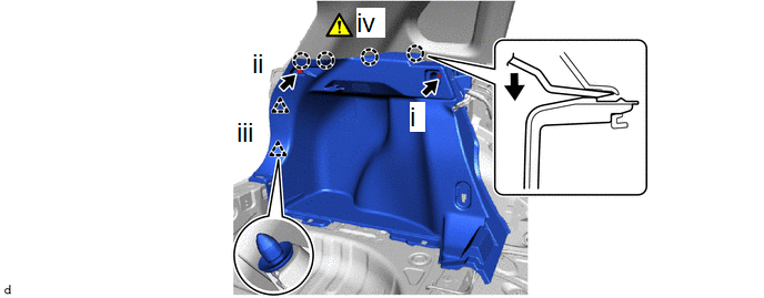
(1) Remove the bolt.
(2) Remove the clip.
(3) Disengage the clips.
(4) Using a moulding remover B, disengage the claws to remove the deck trim side panel assembly LH.
36. REMOVE DECK TRIM SIDE PANEL ASSEMBLY RH
(a) Use the same procedure as for the LH side.
37. REMOVE ROOF SIDE INNER GARNISH ASSEMBLY LH
|
|
Remove in this Direction |
- | - |
38. REMOVE ROOF SIDE INNER GARNISH ASSEMBLY RH
(a) Use the same procedure as for the LH side.
39. REMOVE MAP LIGHT ASSEMBLY (w/o Sliding Roof)
|
|
Click here |
40. REMOVE MAP LIGHT ASSEMBLY (w/ Sliding Roof)
|
|
Click here |
41. REMOVE NO. 1 ROOM LIGHT ASSEMBLY
|
|
Click here |
42. REMOVE VANITY LIGHT ASSEMBLY (w/ Vanity Light)
|
|
Click here |
43. REMOVE NO. 2 FORWARD RECOGNITION COVER
|
|
Click here |
44. REMOVE NO. 1 FORWARD RECOGNITION COVER
|
|
Click here |
45. REMOVE ASSIST GRIP COVER
|
*a | Cutout |
*b | 30 to 45° |
|
|
Pull |
|
Pull in this Direction |
(1) Insert SST into the cutout of the assist grip cover as shown in the illustration.
SST: 09813-00010
NOTICE:
To prevent the assist grip assembly from being damaged, make sure to insert SST straight into the cutout.
(2) Pull SST as shown in the illustration to disengage the claws.
NOTICE:
To prevent the assist grip assembly from being damaged, make sure to only pull SST as shown in the illustration.
(3) Remove the assist grip cover.
(b) Use the same procedure for the opposite side.
46. REMOVE ASSIST GRIP SUB-ASSEMBLY

|
|
Remove in this Direction |
- | - |
(b) Use the same procedure for the opposite side.
47. REMOVE REAR ASSIST GRIP ASSEMBLY LH
(a) Use the same procedure as for the assist grip sub-assembly.
48. REMOVE REAR ASSIST GRIP ASSEMBLY RH
(a) Use the same procedure as for the assist grip sub-assembly.
49. REMOVE VISOR ASSEMBLY LH

50. REMOVE VISOR ASSEMBLY RH
(a) Use the same procedure as for the LH side.
51. REMOVE VISOR HOLDER
|
|
Remove in this Direction (1) |
|
Remove in this Direction (2) |
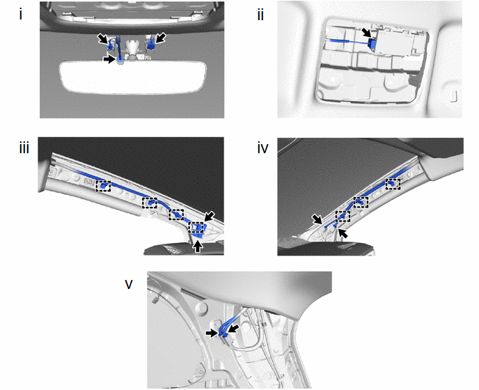
52. REMOVE ROOF HEADLINING ASSEMBLY (w/o Sliding Roof)
HINT:
The illustrations are representative examples, and details may differ.
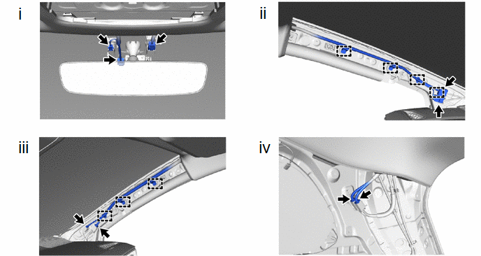
(1) for Windshield Glass Side:
1. Disconnect each connector.
(2) for Front Pillar LH Side:
1. Remove the protective cover.
2. Disengage the clamps.
3. Disconnect the 2 connectors.
4. Install the protective cover.
(3) for Front Pillar RH Side:
1. Remove the protective cover.
2. Disengage the clamps.
3. Disconnect the 2 connectors.
4. Install the protective cover.
(4) for Rear Pillar RH Side:
1. Disconnect the 2 connectors.
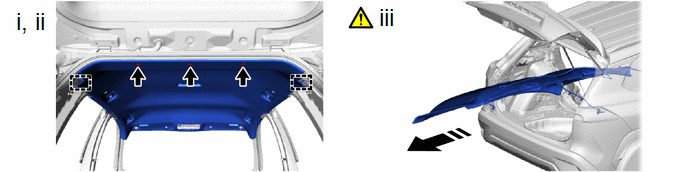
|
|
Remove in this Direction |
- | - |
(1) Remove the 3 clips.
(2) Disengage the guides.
(3) Remove the roof headlining assembly from the vehicle through the back door as shown in the illustration.
NOTICE:
Do not damage the roof headlining assembly or vehicle interior.
53. REMOVE ROOF HEADLINING ASSEMBLY (w/ Sliding Roof)
HINT:
The illustrations are representative examples, and details may differ.
(1) for Windshield Glass Side:
1. Disconnect each connector.
(2) for Map Light Side:
1. Disconnect the connector.
(3) for Front Pillar LH Side:
1. Remove the protective cover.
2. Disengage the clamps.
3. Disconnect the 2 connectors.
4. Install the protective cover.
(4) for Front Pillar RH Side:
1. Remove the protective cover.
2. Disengage the clamps.
3. Disconnect the 2 connectors.
4. Install the protective cover.
(5) for Rear Pillar RH Side:
1. Disconnect the 2 connectors.
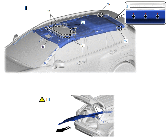
|
*a | Fastener |
*b | Guide |
|
|
Remove in this Direction |
- | - |
(1) Remove the 3 clips.
(2) Disengage the guides and fasteners.
(3) Remove the roof headlining assembly from the vehicle through the back door as shown in the illustration.
NOTICE:
Do not damage the roof headlining assembly or vehicle interior.
54. REMOVE CENTER FLOOR CROSSMEMBER GUSSET SUB-ASSEMBLY