Toyota Corolla Cross: Removal
REMOVAL
CAUTION / NOTICE / HINT
COMPONENTS (REMOVAL)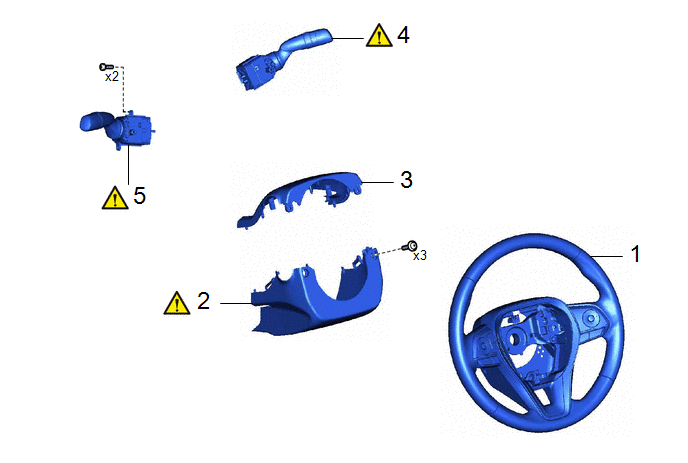
|
Procedure | Part Name Code |
.png) |
.png) |
 |
|---|---|---|---|---|---|
|
1 | STEERING WHEEL ASSEMBLY |
45100 | - |
- | - |
|
2 | LOWER STEERING COLUMN COVER |
45287 |
|
- | - |
|
3 | UPPER STEERING COLUMN COVER |
45286B | - |
- | - |
|
4 | WINDSHIELD WIPER SWITCH ASSEMBLY |
84650 |
|
- | - |
|
5 | TURN SIGNAL SWITCH |
84329 |
|
- | - |
|
Procedure | Part Name Code |
|
|
| |
|---|---|---|---|---|---|
|
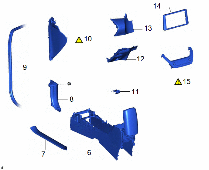
6 | CONSOLE BOX ASSEMBLY |
58810J | - |
- | - |
|
7 | FRONT DOOR SCUFF PLATE LH |
67914B | - |
- | - |
|
8 | COWL SIDE TRIM SUB-ASSEMBLY LH |
62112A | - |
- | - |
|
9 | FRONT DOOR OPENING TRIM WEATHERSTRIP LH |
62312B | - |
- | - |
|
10 | NO. 1 INSTRUMENT SIDE PANEL |
55317E |
|
- | - |
|
11 | HOOD LOCK CONTROL LEVER SUB-ASSEMBLY |
53601 | - |
- | - |
|
12 | LOWER NO. 1 INSTRUMENT PANEL FINISH PANEL |
55432D | - |
- | - |
|
13 | INSTRUMENT PANEL FINISH PANEL SUB-ASSEMBLY |
55403F | - |
- | - |
|
14 | CENTER INSTRUMENT CLUSTER FINISH PANEL SUB-ASSEMBLY |
55405B | - |
- | - |
|
15 | AIR CONDITIONING CONTROL ASSEMBLY |
55900 |
|
- | - |
|
Procedure | Part Name Code |
|
|
| |
|---|---|---|---|---|---|
|
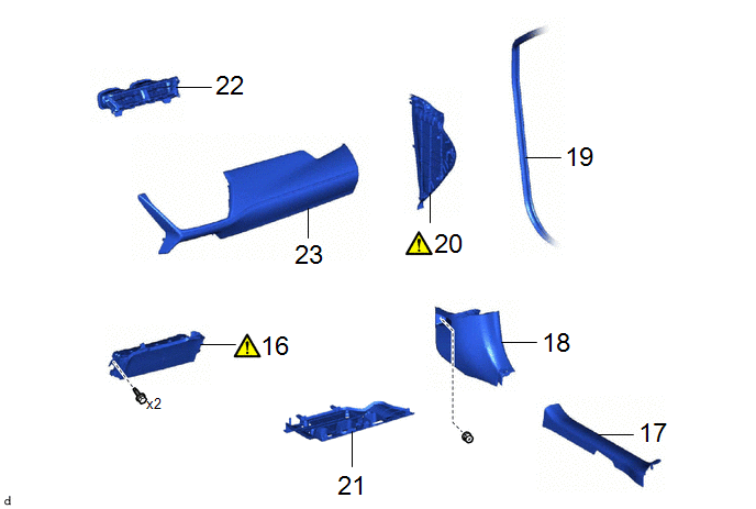
16 | LOWER NO. 1 INSTRUMENT PANEL AIRBAG ASSEMBLY |
73900 |
|
- | - |
|
17 | FRONT DOOR SCUFF PLATE RH |
67913 | - |
- | - |
|
18 | COWL SIDE TRIM SUB-ASSEMBLY RH |
62111C | - |
- | - |
|
19 | FRONT DOOR OPENING TRIM WEATHERSTRIP RH |
62311B | - |
- | - |
|
20 | NO. 2 INSTRUMENT SIDE PANEL |
55318F |
|
- | - |
|
21 | NO. 2 INSTRUMENT PANEL UNDER COVER SUB-ASSEMBLY |
55607 | - |
- | - |
|
22 | CENTER INSTRUMENT PANEL REGISTER ASSEMBLY |
55670A | - |
- | - |
|
23 | INSTRUMENT CLUSTER FINISH PANEL GARNISH ASSEMBLY |
55470 | - |
- | - |
|
Procedure | Part Name Code |
|
|
| |
|---|---|---|---|---|---|
|
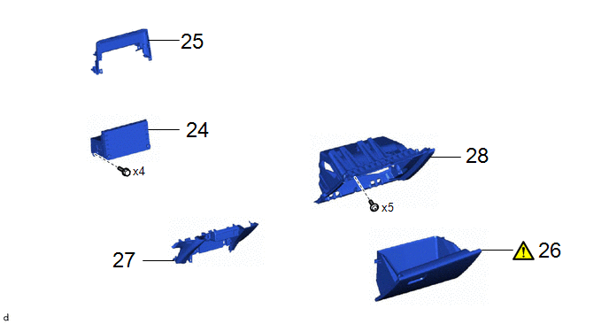
24 | RADIO AND DISPLAY RECEIVER ASSEMBLY WITH BRACKET |
- | - |
- | - |
|
25 | CENTER UPPER INSTRUMENT CLUSTER FINISH PANEL |
55422C | - |
- | - |
|
26 | GLOVE COMPARTMENT DOOR ASSEMBLY |
55550 |
|
- | - |
|
27 | LOWER CENTER INSTRUMENT PANEL FINISH PANEL |
55434F | - |
- | - |
|
28 | NO. 2 LOWER INSTRUMENT PANEL FINISH PANEL |
55433B | - |
- | - |
|
Procedure | Part Name Code |
|
|
| |
|---|---|---|---|---|---|
|
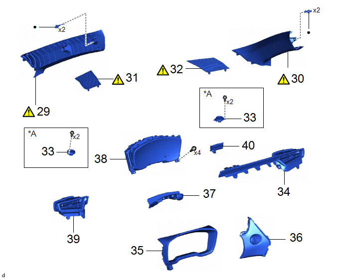
29 | FRONT PILLAR GARNISH ASSEMBLY LH |
62212B |
|
- | - |
|
30 | FRONT PILLAR GARNISH ASSEMBLY RH |
62211U |
|
- | - |
|
31 | NO. 1 INSTRUMENT PANEL SPEAKER PANEL |
55472C |
|
- | - |
|
32 | NO. 2 INSTRUMENT PANEL SPEAKER PANEL |
55473B |
|
- | - |
|
33 | FRONT NO. 2 SPEAKER ASSEMBLY |
86160P | - |
- | - |
|
34 | NO. 1 INSTRUMENT PANEL GARNISH SUB-ASSEMBLY |
55011A | - |
- | - |
|
35 | INSTRUMENT CLUSTER FINISH PANEL ASSEMBLY |
55410C | - |
- | - |
|
36 | CENTER LOWER INSTRUMENT CLUSTER FINISH PANEL |
55413D | - |
- | - |
|
37 | INSTRUMENT CLUSTER FINISH PANEL RETAINER |
55416C | - |
- | - |
|
38 | COMBINATION METER ASSEMBLY |
83100 | - |
- | - |
|
39 | NO. 2 INSTRUMENT CLUSTER FINISH PANEL GARNISH |
55475A | - |
- | - |
|
40 | INSTRUMENT CLUSTER FINISH PANEL GARNISH |
55474B | - |
- | - |
|
*A | w/ Stereo Component Amplifier |
- | - |
|
● | Non-reusable part |
- | - |
|
Procedure | Part Name Code |
|
|
| |
|---|---|---|---|---|---|
|
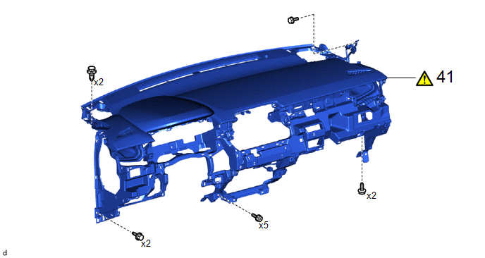
41 | INSTRUMENT PANEL SAFETY PAD SUB-ASSEMBLY |
- |
|
- | - |
CAUTION / NOTICE / HINT
HINT:
When the cable is disconnected/reconnected to the auxiliary battery terminal, systems temporarily stop operating. However, each system has a function that completes learning the first time the system is used.
- Learning completes when vehicle is driven
Effect/Inoperative Function When Necessary Procedures are not Performed
Necessary Procedures
Link
*1: for Gasoline Model Front Camera System
Drive the vehicle straight ahead at 15 km/h (10 mph) or more for 1 second or more.
.gif)
Stop and start system*1
Drive the vehicle until stop and start control is permitted (approximately 5 to 60 minutes)
- Learning completes when vehicle is operated normally
Effect/Inoperative Function When Necessary Procedures are not Performed
Necessary Procedures
Link
Power door lock control system
- Back door opener
Perform door unlock operation with door control switch or electrical key transmitter sub-assembly switch.
Power back door system
Fully close the back door by hand.
HINT:
Initialization is not necessary if the above procedures are performed while the back door is closed.
Air conditioning system
After the ignition switch is turned to ON, the servo motor standard position is recognized.
-
PROCEDURE
1. REMOVE STEERING WHEEL ASSEMBLY
Click here
2. REMOVE LOWER STEERING COLUMN COVER
|
|
Click here |
3. REMOVE UPPER STEERING COLUMN COVER
Click here
4. REMOVE WINDSHIELD WIPER SWITCH ASSEMBLY
|
|
Click here |
5. REMOVE TURN SIGNAL SWITCH
|
|
Click here |
6. REMOVE CONSOLE BOX ASSEMBLY
Click here
7. REMOVE FRONT DOOR SCUFF PLATE LH
Click here
8. REMOVE COWL SIDE TRIM SUB-ASSEMBLY LH
Click here
9. DISCONNECT FRONT DOOR OPENING TRIM WEATHERSTRIP LH

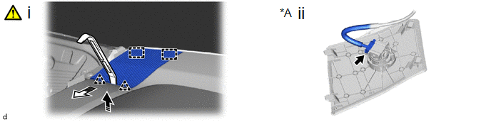
10. REMOVE NO. 1 INSTRUMENT SIDE PANEL
.png) |
Remove in this Direction (1) |
.png) |
Remove in this Direction (2) |
(1) Using a moulding remover B, disengage the clips and guides to remove the No. 1 instrument side panel as shown in the illustration.
11. DISCONNECT HOOD LOCK CONTROL LEVER SUB-ASSEMBLY

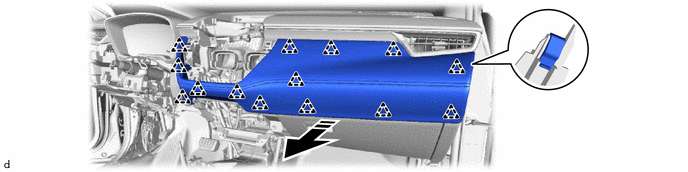
12. REMOVE LOWER NO. 1 INSTRUMENT PANEL FINISH PANEL
HINT:
The illustrations are representative examples, and details may differ.
|
|
Remove in this Direction |
- | - |
13. REMOVE INSTRUMENT PANEL FINISH PANEL SUB-ASSEMBLY
|
|
Remove in this Direction |
- | - |
14. REMOVE CENTER INSTRUMENT CLUSTER FINISH PANEL SUB-ASSEMBLY
|
|
Remove in this Direction |
- | - |
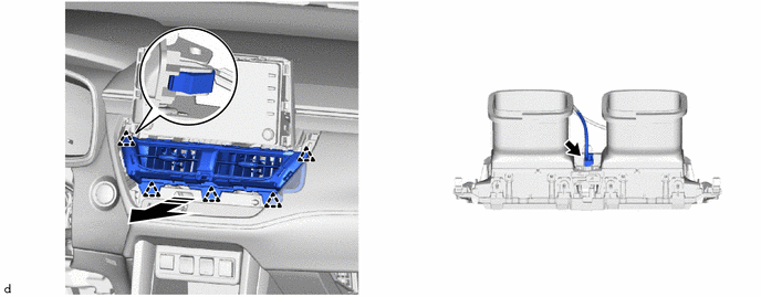
15. REMOVE AIR CONDITIONING CONTROL ASSEMBLY
|
|
Click here |
16. REMOVE LOWER NO. 1 INSTRUMENT PANEL AIRBAG ASSEMBLY
|
|
Click here |
17. REMOVE FRONT DOOR SCUFF PLATE RH
(a) Use the same procedure as for the LH side.
18. REMOVE COWL SIDE TRIM SUB-ASSEMBLY RH
(a) Use the same procedure as for the LH side.
19. DISCONNECT FRONT DOOR OPENING TRIM WEATHERSTRIP RH
(a) Use the same procedure as for the LH side.
20. REMOVE NO. 2 INSTRUMENT SIDE PANEL
(a) Use the same procedure as for the No. 1 instrument side panel.
21. REMOVE NO. 2 INSTRUMENT PANEL UNDER COVER SUB-ASSEMBLY
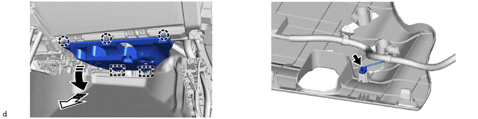
|
|
Remove in this Direction (1) |
|
Remove in this Direction (2) |
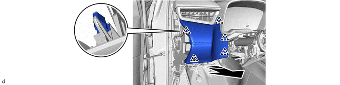
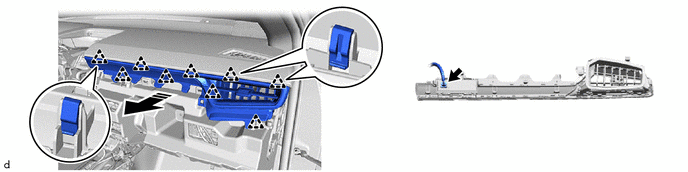
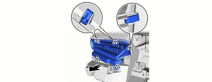
22. REMOVE CENTER INSTRUMENT PANEL REGISTER ASSEMBLY
|
|
Remove in this Direction |
- | - |
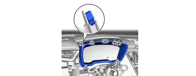
23. REMOVE INSTRUMENT CLUSTER FINISH PANEL GARNISH ASSEMBLY
|
|
Remove in this Direction |
- | - |
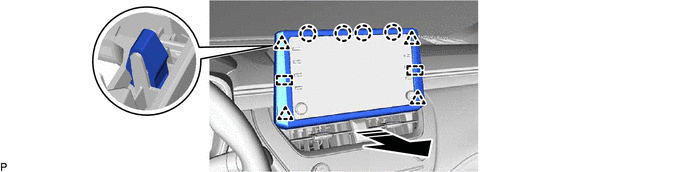
24. REMOVE RADIO AND DISPLAY RECEIVER ASSEMBLY WITH BRACKET
Click here
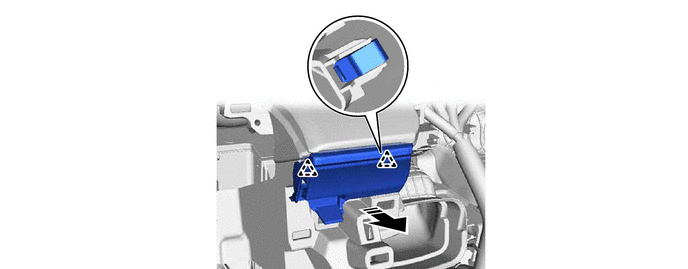
25. REMOVE CENTER UPPER INSTRUMENT CLUSTER FINISH PANEL

|
|
Remove in this Direction |
- | - |
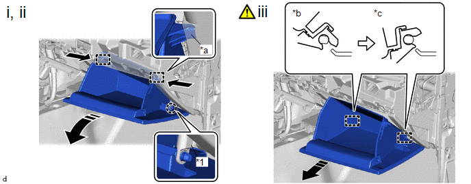
26. REMOVE GLOVE COMPARTMENT DOOR ASSEMBLY
|
*1 | Glove Compartment Door Stopper Sub-assembly |
- | - |
|
*a | Stopper |
*b | Closed |
|
*c | Open Approximately 57° |
- | - |
.png) |
Slightly Bend |
|
Remove in this Direction |
(1) Disengage the claw to disconnect the glove compartment door stopper sub-assembly.
(2) Slightly bend the stoppers in the directions indicated by the arrows in the illustration and open the glove compartment door assembly until the stoppers are released.
(3) Open the glove compartment door assembly to approximately 57° from its closed position. Pull it horizontally in the direction indicated by the arrow to disengage the hinges and remove the glove compartment door assembly.
NOTICE:
Pulling the glove compartment door assembly upward to remove it causes the hinges to deform. Be sure to pull out the glove compartment door assembly horizontally.
27. REMOVE LOWER CENTER INSTRUMENT PANEL FINISH PANEL
HINT:
The illustrations are representative examples, and details may differ.
|
|
Remove in this Direction |
- | - |
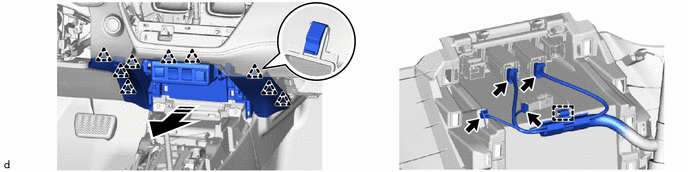
28. REMOVE LOWER NO. 2 INSTRUMENT PANEL FINISH PANEL
|
*A | w/ Illumination |
- | - |
|
|
Remove in this Direction |
- | - |
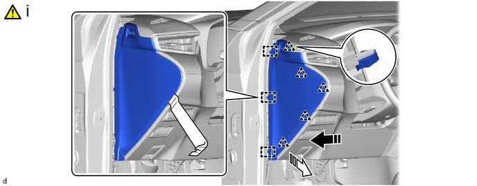
29. REMOVE FRONT PILLAR GARNISH ASSEMBLY LH
|
|
Click here |
30. REMOVE FRONT PILLAR GARNISH ASSEMBLY RH
(a) Use the same procedure as for the LH side.
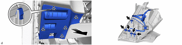
31. REMOVE NO. 1 INSTRUMENT PANEL SPEAKER PANEL
|
*A | w/o Stereo Component Amplifier |
- | - |
|
|
Remove in this Direction (1) |
|
Remove in this Direction (2) |
(1) Using a moulding remover A, disengage the clips and guides to remove the No. 1 instrument panel speaker panel as shown in the illustration.
(2) w/o Stereo Component Amplifier:
1. Disconnect the connector.
32. REMOVE NO. 2 INSTRUMENT PANEL SPEAKER PANEL
(a) Use the same procedure as for the No. 1 instrument panel speaker panel.
33. REMOVE FRONT NO. 2 SPEAKER ASSEMBLY (w/ Stereo Component Amplifier)
Click here
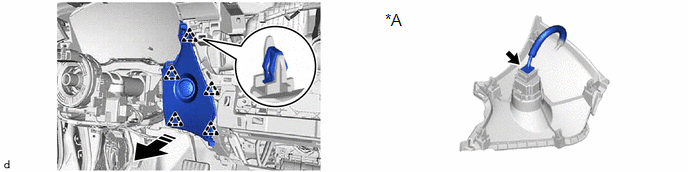
34. REMOVE NO. 1 INSTRUMENT PANEL GARNISH SUB-ASSEMBLY
|
|
Remove in this Direction |
- | - |
35. REMOVE INSTRUMENT CLUSTER FINISH PANEL ASSEMBLY
36. REMOVE CENTER LOWER INSTRUMENT CLUSTER FINISH PANEL
|
*A | w/ Smart Key System |
- | - |
|
|
Remove in this Direction |
- | - |
37. REMOVE INSTRUMENT CLUSTER FINISH PANEL RETAINER

|
|
Remove in this Direction |
- | - |
38. REMOVE COMBINATION METER ASSEMBLY
Click here
39. REMOVE NO. 2 INSTRUMENT CLUSTER FINISH PANEL GARNISH
|
|
Remove in this Direction |
- | - |
40. REMOVE INSTRUMENT CLUSTER FINISH PANEL GARNISH
|
|
Remove in this Direction |
- | - |
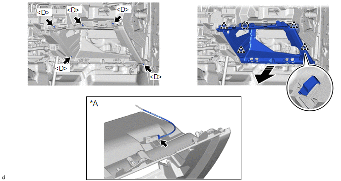
41. REMOVE INSTRUMENT PANEL SAFETY PAD SUB-ASSEMBLY
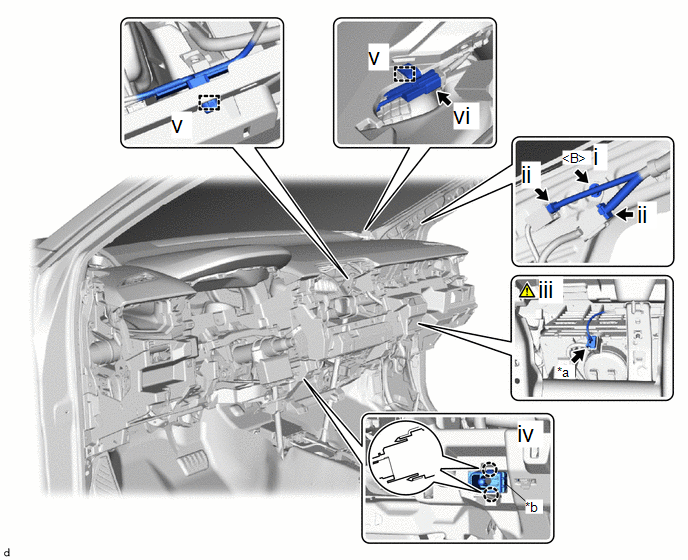
|
*a | Airbag Connector |
*b | Cooler Thermistor (Room Temperature Sensor) |
(1) Remove the bolt <B>.
(2) Disconnect the 2 connectors.
(3) Disconnect the airbag connector.
NOTICE:
When disconnecting any airbag connector, take care not to damage the airbag wire harness.
HINT:
Refer to How to Connect or Disconnect Airbag Connector:
Click here
(4) Disengage the claws to disconnect the cooler thermistor (room temperature sensor).
(5) Disengage the clamps.
(6) Disconnect the connector.
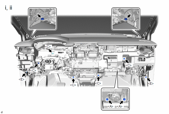
(1) Remove the 2 clips.
(2) Remove the 2 bolts <A>, 2 bolts <E> and 5 screws <C>.
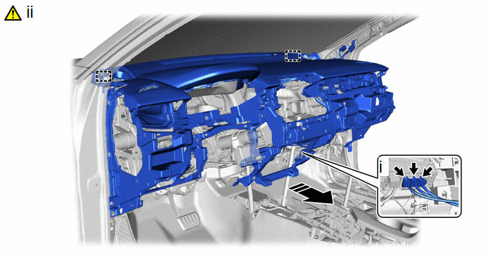
|
|
Remove in this Direction |
- | - |
(1) Disconnect the 3 connectors.
(2) Disengage the guides to remove the instrument panel safety pad sub-assembly as shown in the illustration.
NOTICE:
- Do not damage the instrument panel safety pad sub-assembly.
- Do not allow the wire harnesses to interfere with the surrounding parts.


