Toyota Corolla Cross: Installation
INSTALLATION
CAUTION / NOTICE / HINT
COMPONENTS (INSTALLATION)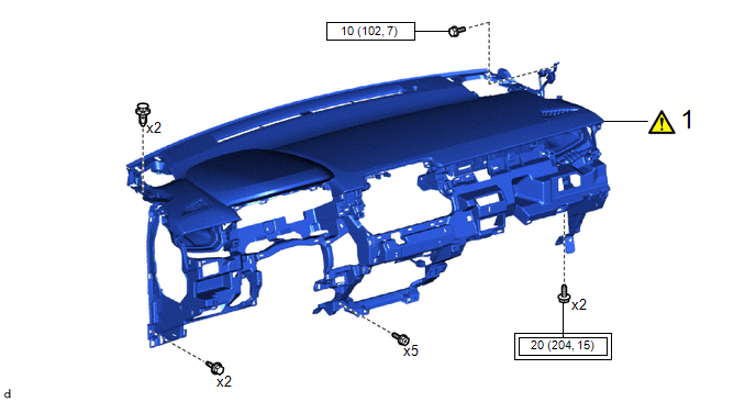
|
Procedure | Part Name Code |
.png) |
.png) |
 |
|---|---|---|---|---|---|
|
1 | INSTRUMENT PANEL SAFETY PAD SUB-ASSEMBLY |
- |
|
- | - |
.png) |
Tightening torque for "Major areas involving basic vehicle performance such as moving/turning/stopping" : N*m (kgf*cm, ft.*lbf) |
.png) |
N*m (kgf*cm, ft.*lbf): Specified torque |
|
Procedure | Part Name Code |
|
|
| |
|---|---|---|---|---|---|
|
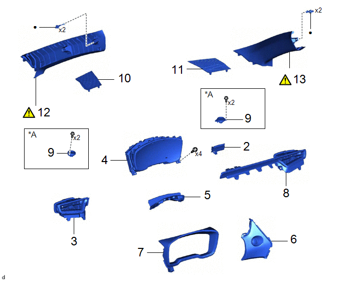
2 | INSTRUMENT CLUSTER FINISH PANEL GARNISH |
55474B | - |
- | - |
|
3 | NO. 2 INSTRUMENT CLUSTER FINISH PANEL GARNISH |
55475A | - |
- | - |
|
4 | COMBINATION METER ASSEMBLY |
83100 | - |
- | - |
|
5 | INSTRUMENT CLUSTER FINISH PANEL RETAINER |
55416C | - |
- | - |
|
6 | CENTER LOWER INSTRUMENT CLUSTER FINISH PANEL |
55413D | - |
- | - |
|
7 | INSTRUMENT CLUSTER FINISH PANEL ASSEMBLY |
55410C | - |
- | - |
|
8 | NO. 1 INSTRUMENT PANEL GARNISH SUB-ASSEMBLY |
55011A | - |
- | - |
|
9 | FRONT NO. 2 SPEAKER ASSEMBLY |
86160P | - |
- | - |
|
10 | NO. 1 INSTRUMENT PANEL SPEAKER PANEL |
55472C | - |
- | - |
|
11 | NO. 2 INSTRUMENT PANEL SPEAKER PANEL |
55473B | - |
- | - |
|
12 | FRONT PILLAR GARNISH ASSEMBLY LH |
62212B |
|
- | - |
|
13 | FRONT PILLAR GARNISH ASSEMBLY RH |
62211U |
|
- | - |
|
*A | w/ Stereo Component Amplifier |
- | - |
|
● | Non-reusable part |
- | - |
|
Procedure | Part Name Code |
|
|
| |
|---|---|---|---|---|---|
|
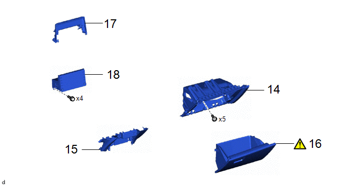
14 | LOWER NO. 2 INSTRUMENT PANEL FINISH PANEL |
55433B | - |
- | - |
|
15 | LOWER CENTER INSTRUMENT PANEL FINISH PANEL |
55434F | - |
- | - |
|
16 | GLOVE COMPARTMENT DOOR ASSEMBLY |
55550 |
|
- | - |
|
17 | CENTER UPPER INSTRUMENT CLUSTER FINISH PANEL |
55422C | - |
- | - |
|
18 | RADIO AND DISPLAY RECEIVER ASSEMBLY WITH BRACKET |
- | - |
- | - |
|
Procedure | Part Name Code |
|
|
| |
|---|---|---|---|---|---|
|
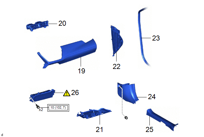
19 | INSTRUMENT CLUSTER FINISH PANEL GARNISH ASSEMBLY |
55470 | - |
- | - |
|
20 | CENTER INSTRUMENT PANEL REGISTER ASSEMBLY |
55670A | - |
- | - |
|
21 | NO. 2 INSTRUMENT PANEL UNDER COVER SUB-ASSEMBLY |
55607 | - |
- | - |
|
22 | NO. 2 INSTRUMENT SIDE PANEL |
55318F | - |
- | - |
|
23 | FRONT DOOR OPENING TRIM WEATHERSTRIP RH |
62311B | - |
- | - |
|
24 | COWL SIDE TRIM BOARD RH |
62111C | - |
- | - |
|
25 | FRONT DOOR SCUFF PLATE RH |
67913 | - |
- | - |
|
26 | LOWER NO. 1 INSTRUMENT PANEL AIRBAG ASSEMBLY |
73900 |
|
- | - |
|
|
Tightening torque for "Major areas involving basic vehicle performance such as moving/turning/stopping" : N*m (kgf*cm, ft.*lbf) |
- | - |
|
Procedure | Part Name Code |
|
|
| |
|---|---|---|---|---|---|
|
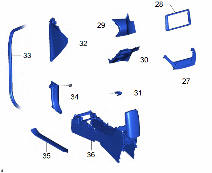
27 | AIR CONDITIONING CONTROL ASSEMBLY |
55900 | - |
- | - |
|
28 | CENTER INSTRUMENT CLUSTER FINISH PANEL SUB-ASSEMBLY |
55405B | - |
- | - |
|
29 | INSTRUMENT PANEL FINISH PANEL SUB-ASSEMBLY |
55403F | - |
- | - |
|
30 | LOWER NO. 1 INSTRUMENT PANEL FINISH PANEL |
55432D | - |
- | - |
|
31 | HOOD LOCK CONTROL LEVER SUB-ASSEMBLY |
53601 | - |
- | - |
|
32 | NO. 1 INSTRUMENT SIDE PANEL |
55317E | - |
- | - |
|
33 | FRONT DOOR OPENING TRIM WEATHERSTRIP LH |
62312B | - |
- | - |
|
34 | COWL SIDE TRIM SUB-ASSEMBLY LH |
62112A | - |
- | - |
|
35 | FRONT DOOR SCUFF PLATE LH |
67914 | - |
- | - |
|
36 | CONSOLE BOX ASSEMBLY |
58810J | - |
- | - |
|
Procedure | Part Name Code |
|
|
| |
|---|---|---|---|---|---|
|
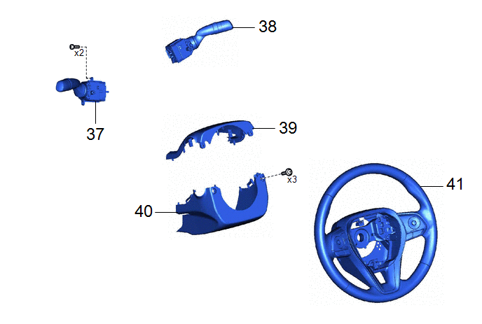
37 | TURN SIGNAL SWITCH |
84329 | - |
- | - |
|
38 | WINDSHIELD WIPER SWITCH ASSEMBLY |
84650 | - |
- | - |
|
39 | UPPER STEERING COLUMN COVER |
45286B | - |
- | - |
|
40 | LOWER STEERING COLUMN COVER |
45287 | - |
- | - |
|
41 | STEERING WHEEL ASSEMBLY |
45100 | - |
- | - |
PROCEDURE
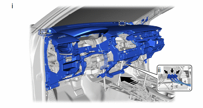
1. INSTALL INSTRUMENT PANEL SAFETY PAD SUB-ASSEMBLY
.png) |
Install in this Direction |
- | - |
(1) Engage the guides to install the instrument panel safety pad sub-assembly as shown in the illustration.
(2) Connect the 3 connectors.
.png)
(1) Install the 5 screws <C>, 2 bolts <E> and 2 bolts <A>.
Torque:
Bolt <A> :
20 N·m {204 kgf·cm, 15 ft·lbf}
(2) Install the 2 clips.
|
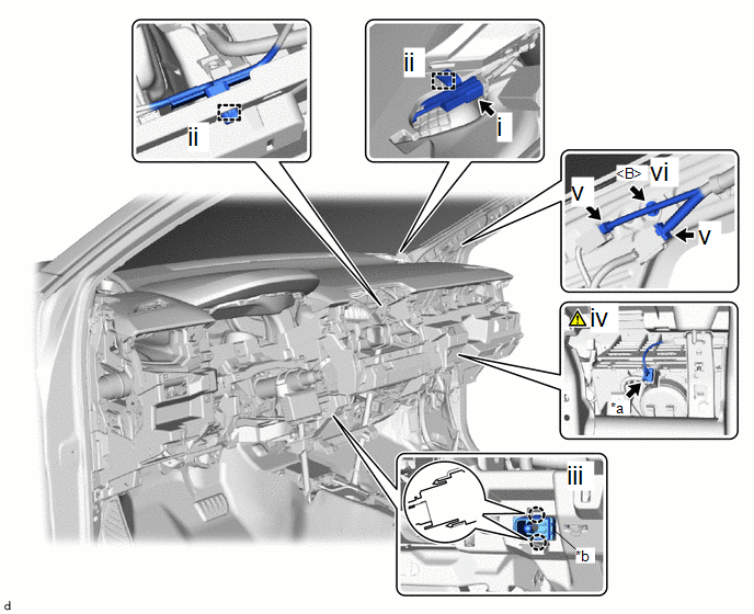
*a | Airbag Connector |
*b | Cooler Thermistor (Room Temperature Sensor) |
(1) Connect the connector.
(2) Engage the clamps.
(3) Engage the claws to connect the cooler thermistor (room temperature sensor).
(4) Connect the airbag connector.
NOTICE:
When disconnecting any airbag connector, take care not to damage the airbag wire harness.
HINT:
Refer to How to Connect or Disconnect Airbag Connector:
Click here
.gif)
(5) Connect the connector.
(6) Install the bolts <B>.
Torque:
10 N·m {102 kgf·cm, 7 ft·lbf}
2. INSTALL INSTRUMENT CLUSTER FINISH PANEL GARNISH
3. INSTALL NO. 2 INSTRUMENT CLUSTER FINISH PANEL GARNISH
4. INSTALL COMBINATION METER ASSEMBLY
5. INSTALL INSTRUMENT CLUSTER FINISH PANEL RETAINER
6. INSTALL INSTRUMENT CLUSTER FINISH PANEL ASSEMBLY
7. INSTALL CENTER LOWER INSTRUMENT CLUSTER FINISH PANEL
8. INSTALL NO. 1 INSTRUMENT PANEL GARNISH SUB-ASSEMBLY
9. INSTALL FRONT NO. 2 SPEAKER ASSEMBLY (w/ Stereo Component Amplifier)
10. INSTALL NO. 1 INSTRUMENT PANEL SPEAKER PANEL
11. INSTALL NO. 2 INSTRUMENT PANEL SPEAKER PANEL
12. INSTALL FRONT PILLAR GARNISH ASSEMBLY LH
|
|
Click here |
13. INSTALL FRONT PILLAR GARNISH ASSEMBLY RH
14. INSTALL LOWER NO. 2 INSTRUMENT PANEL FINISH PANEL
15. INSTALL LOWER CENTER INSTRUMENT PANEL FINISH PANEL
16. INSTALL GLOVE COMPARTMENT DOOR ASSEMBLY
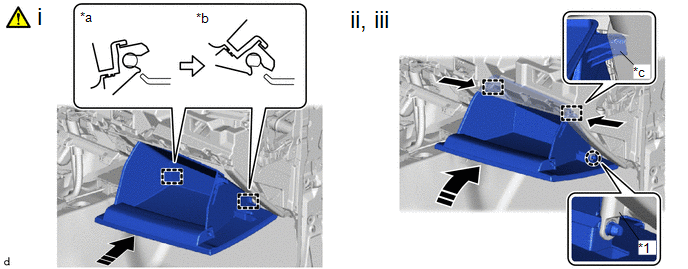
|
*1 | Glove Compartment Door Stopper Sub-assembly |
- | - |
|
*a | Open Approximately 57° |
*b | Closed |
|
*c | Stopper |
- | - |
.png) |
Slightly Bend |
|
Install in this Direction |
(1) With the glove compartment door assembly opened approximately 57° from its closed position, engage the hinges horizontally.
NOTICE:
Engaging the hinges from the top will deform the hinges. Be sure to install the glove compartment door assembly horizontally.
(2) Slightly bend the stoppers in the directions indicated by the arrow in the illustration and engage the stoppers to install the glove compartment door assembly.
(3) Engage the claw to connect the glove compartment door stopper sub-assembly.
17. INSTALL CENTER UPPER INSTRUMENT CLUSTER FINISH PANEL
18. INSTALL RADIO AND DISPLAY RECEIVER ASSEMBLY WITH BRACKET
19. INSTALL INSTRUMENT CLUSTER FINISH PANEL GARNISH ASSEMBLY
20. INSTALL CENTER INSTRUMENT PANEL REGISTER ASSEMBLY
21. INSTALL NO. 2 INSTRUMENT PANEL UNDER COVER SUB-ASSEMBLY
22. INSTALL NO. 2 INSTRUMENT SIDE PANEL
23. INSTALL FRONT DOOR OPENING TRIM WEATHERSTRIP RH
24. INSTALL COWL SIDE TRIM BOARD RH
25. INSTALL FRONT DOOR SCUFF PLATE RH
26. INSTALL LOWER NO. 1 INSTRUMENT PANEL AIRBAG ASSEMBLY
|
|
Click here |
27. INSTALL AIR CONDITIONING CONTROL ASSEMBLY
28. INSTALL CENTER INSTRUMENT CLUSTER FINISH PANEL SUB-ASSEMBLY
29. INSTALL INSTRUMENT PANEL FINISH PANEL SUB-ASSEMBLY
30. INSTALL LOWER NO. 1 INSTRUMENT PANEL FINISH PANEL
31. CONNECT HOOD LOCK CONTROL LEVER SUB-ASSEMBLY
32. INSTALL NO. 1 INSTRUMENT SIDE PANEL
33. INSTALL FRONT DOOR OPENING TRIM WEATHERSTRIP LH
34. INSTALL COWL SIDE TRIM SUB-ASSEMBLY LH
35. INSTALL FRONT DOOR SCUFF PLATE LH
36. INSTALL CONSOLE BOX ASSEMBLY
Click here
37. INSTALL TURN SIGNAL SWITCH
38. INSTALL WINDSHIELD WIPER SWITCH ASSEMBLY
39. INSTALL UPPER STEERING COLUMN COVER
40. INSTALL LOWER STEERING COLUMN COVER
41. INSTALL STEERING WHEEL ASSEMBLY
Click here


