Toyota Corolla Cross: Reassembly
REASSEMBLY
CAUTION / NOTICE / HINT
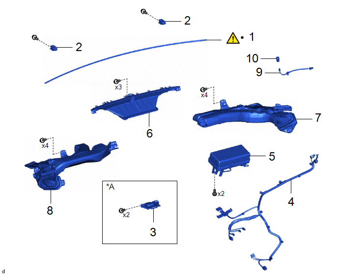
COMPONENTS (REASSEMBLY)
|
Procedure | Part Name Code |
.png) |
.png) |
 |
|---|---|---|---|---|---|
|
1 | INSTRUMENT PANEL CUSHION |
55349A |
|
- | - |
|
2 | NO. 1 INSTRUMENT PANEL PIN |
55328 | - |
- | - |
|
3 | NAVIGATION ANTENNA ASSEMBLY WITH BRACKET |
- | - |
- | - |
|
4 | ANTENNA CORD SUB-ASSEMBLY |
86101 | - |
- | - |
|
5 | INSTRUMENT PANEL PASSENGER AIRBAG ASSEMBLY |
73960A | - |
- | - |
|
6 | DEFROSTER NOZZLE ASSEMBLY |
55950G | - |
- | - |
|
7 | NO. 2 HEATER TO REGISTER DUCT SUB-ASSEMBLY |
55085 | - |
- | - |
|
8 | NO. 1 HEATER TO REGISTER DUCT SUB-ASSEMBLY |
55084E | - |
- | - |
|
9 | NO. 2 INSTRUMENT PANEL WIRE |
82142A | - |
- | - |
|
10 | AUTOMATIC LIGHT CONTROL SENSOR |
89120A | - |
- | - |
|
*A | w/ Navigation Antenna |
- | - |
|
● | Non-reusable part |
- | - |
PROCEDURE
1. INSTALL INSTRUMENT PANEL CUSHION

|
*a | Edge of Curved Surface |
*b | Outline |
(1) Clean the upper instrument panel assembly surface by the below procedure.
1. Remove any remaining double-sided tape from the upper instrument panel assembly.
2. Wipe off any tape adhesive residue with cleaner.
(2) Remove the release paper from a new instrument panel cushion.
HINT:
After removing the release paper, keep the exposed adhesive free from foreign matter.
(3) Install the instrument panel cushion as shown in the illustration.
2. INSTALL NO. 1 INSTRUMENT PANEL PIN
3. INSTALL ANTENNA CORD SUB-ASSEMBLY
4. INSTALL NAVIGATION ANTENNA ASSEMBLY WITH BRACKET
5. INSTALL INSTRUMENT PANEL PASSENGER AIRBAG ASSEMBLY
6. INSTALL DEFROSTER NOZZLE ASSEMBLY
7. INSTALL NO. 2 HEATER TO REGISTER DUCT SUB-ASSEMBLY
8. INSTALL NO. 1 HEATER TO REGISTER DUCT SUB-ASSEMBLY
9. INSTALL NO. 2 INSTRUMENT PANEL WIRE
10. INSTALL AUTOMATIC LIGHT CONTROL SENSOR

.gif)

