Toyota Corolla Cross: Intake Air Temperature Sensor 1 Bank 1 Circuit Short to Battery or Open (P011015)
DESCRIPTION
Refer to DTC P011011.
Click here
.gif)
HINT:
When DTC P011015 is stored, the ECM enters fail-safe mode. During fail-safe mode, the intake air temperature is estimated to be 20°C (68°F) by the ECM. Fail-safe mode continues until a pass condition is detected, and the ignition switch is then turned off.
|
DTC No. | Detection Item |
DTC Detection Condition | Trouble Area |
MIL | Note |
|---|---|---|---|---|---|
|
P011015 | Intake Air Temperature Sensor 1 Bank 1 Circuit Short to Battery or Open |
Diagnosis condition:
Abnormal condition:
Malfunction time:
Trip logic:
Detection conditions:
Sensors/components used for detection:
|
| Comes on |
|
HINT:
When this DTC is output, check the intake air temperature in the Data List. Enter the following menus: Powertrain / Engine / Data List / Intake Air Temperature.
|
DTC No. | Intake Air Temperature |
Malfunction |
|---|---|---|
| P011015 |
-40°C (-40°F) |
|
If the Data List values is normal it may be due to a temporary recovery from the malfunction condition. Check for intermittent problems.
Click here
MONITOR DESCRIPTION
When the ignition switch is turned ON and the output voltage of the intake air temperature sensor is higher than 4.91 V for 0.5 seconds or more, the ECM determines that the intake air temperature sensor circuit is malfunctioning and illuminates the MIL and stores a DTC.
MONITOR STRATEGY
|
Related DTCs | P0113: Intake air temperature sensor range check (high voltage) |
|
Required Sensors/Components (Main) | Intake air temperature sensor |
|
Required Sensors/Components (Related) |
- |
| Frequency of Operation |
Continuous |
| Duration |
0.5 seconds |
| MIL Operation |
Immediate |
| Sequence of Operation |
None |
TYPICAL ENABLING CONDITIONS
|
Monitor runs whenever the following DTCs are not stored |
None |
| All of the following conditions are met |
- |
| Auxiliary battery voltage |
8 V or higher |
| Ignition switch |
ON |
| Starter |
Off |
TYPICAL MALFUNCTION THRESHOLDS
|
Intake air temperature sensor voltage [Intake air temperature] |
Higher than 4.91 V [Less than -55°C (-67°F)] |
CONFIRMATION DRIVING PATTERN
Refer to DTC P011011.
Click here
WIRING DIAGRAM
Refer to DTC P010012.
Click here
CAUTION / NOTICE / HINT
HINT:
Read Freeze Frame Data using the GTS. The ECM records vehicle and driving condition information as Freeze Frame Data the moment a DTC is stored. When troubleshooting, Freeze Frame Data can help determine if the vehicle was moving or stationary, if the engine was warmed up or not, if the air fuel ratio was lean or rich, and other data from the time the malfunction occurred.
PROCEDURE
| 1. |
CHECK TERMINAL VOLTAGE (INTAKE AIR TEMPERATURE SENSOR) |
|
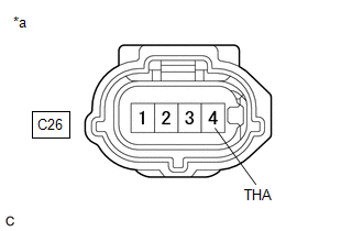
*a | Front view of wire harness connector (to Intake Air Temperature Sensor) |
(a) Disconnect the intake air temperature sensor connector.
(b) Turn the ignition switch to ON.
(c) Measure the voltage according to the value(s) in the table below.
Standard Voltage:
|
Tester Connection | Condition |
Specified Condition |
|---|---|---|
|
C26-4 (THA) - Body ground |
Ignition switch ON | 0 to 5.5 V |
| NG | .gif) | GO TO STEP 4 |
|
.gif)
| 2. |
READ VALUE USING GTS (INTAKE AIR TEMPERATURE) |
|
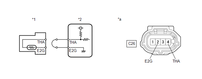
*1 | Intake Air Temperature Sensor |
*2 | ECM |
|
*a | Front view of wire harness connector (to Intake Air Temperature Sensor) |
- | - |
(a) Disconnect the intake air temperature sensor connector.
(b) Connect terminals 4 (THA) and 2 (E2G) of the intake air temperature sensor connector on the wire harness side.
(c) Enter the following menus.
Powertrain > Engine > Data List|
Tester Display |
|---|
| Intake Air Temperature |
(d) According to the display on the GTS, read the Data List.
OK:
|
GTS Display | Specified Condition |
|---|---|
|
Intake Air Temperature |
140°C (284°F) |
HINT:
Perform "Inspection After Repair" after replacing the mass air flow meter sub-assembly.
Click here
| OK | | REPLACE MASS AIR FLOW METER SUB-ASSEMBLY |
|
| 3. |
CHECK HARNESS AND CONNECTOR (INTAKE AIR TEMPERATURE SENSOR - ECM) |
(a) Disconnect the intake air temperature sensor connector.
(b) Disconnect the ECM connector.
(c) Measure the resistance according to the value(s) in the table below.
Standard Resistance:
|
Tester Connection | Condition |
Specified Condition |
|---|---|---|
|
C26-4 (THA) - C76-102 (THA) |
Always | Below 1 Ω |
|
C26-2 (E2G) - C76-79 (E2G) |
Always | Below 1 Ω |
| OK | | REPLACE ECM
|
| NG | | REPAIR OR REPLACE HARNESS OR CONNECTOR |
| 4. |
CHECK HARNESS AND CONNECTOR (INTAKE AIR TEMPERATURE SENSOR - ECM) |
(a) Disconnect the intake air temperature sensor connector.
(b) Disconnect the ECM connector.
(c) Measure the resistance according to the value(s) in the table below.
Standard Resistance:
|
Tester Connection | Condition |
Specified Condition |
|---|---|---|
|
C26-4 (THA) or C76-102 (THA) - Other terminals |
Always | 10 kΩ or higher |
| OK | | REPLACE ECM
|
| NG | | REPAIR OR REPLACE HARNESS OR CONNECTOR |
READ NEXT:
 Intake Air Temperature Sensor 1 Bank 1 Signal Stuck in Range (P01102A)
DESCRIPTION Refer to DTC P011011. Click here
DTC No. Detection Item
DTC Detection Condition Trouble Area
MIL Note
P01102A Intake Air Temperature Sensor 1 Bank 1 Sig
Engine Coolant Temperature Sensor 1 Circuit Short to Ground (P011511)
DESCRIPTION A thermistor, whose resistance value varies according to the engine coolant temperature, is built into the engine coolant temperature sensor. The structure of the sensor and its connection
Engine Coolant Temperature Sensor 1 Circuit Short to Battery or Open (P011515)
DESCRIPTION Refer to DTC P011511. Click here
HINT: When DTC P011515 is stored, the ECM enters fail-safe mode. During fail-safe mode, the engine coolant temperature is estimated to be 80°C (176°F
SEE MORE:
 Driver Frontal Stage 1 Deployment Control Circuit Short to Battery (B000112)
DESCRIPTION
DTC No. Detection Item
DTC Detection Condition Trouble Area
Warning Indicate Test Mode / Check Mode
B000112 Driver Frontal Stage 1 Deployment Control Circuit Short to Battery
One of the following conditions is met:
The airbag ECU assembly de
Tachometer Malfunction
DESCRIPTION for HEV Model:
The combination meter assembly receives engine speed signals from the hybrid vehicle control ECU via CAN communication. The combination meter assembly displays the engine speed calculated based on the data received from the hybrid vehicle control ECU.
for Gasoline
