Toyota Corolla Cross: Removal
REMOVAL
CAUTION / NOTICE / HINT
COMPONENTS (REOVAL)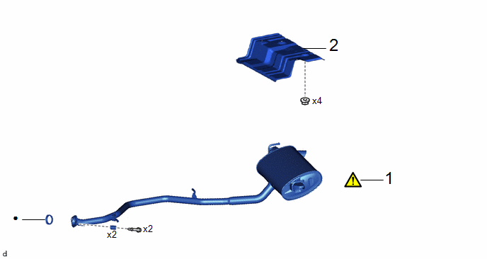
|
Procedure |
Part Name Code |
.png) |
.png) |
.png) |
|
|---|---|---|---|---|---|
|
1 |
TAIL EXHAUST PIPE ASSEMBLY |
17430 |
|
- |
- |
|
2 |
MAIN MUFFLER HEAT INSULATOR UPPER |
58327D |
- |
- |
- |
|
● |
Non-reusable part |
- |
- |
|
Procedure |
Part Name Code |
|
|
|
|
|---|---|---|---|---|---|
|
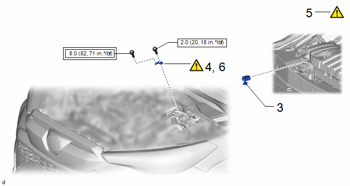
3 |
SERVICE PLUG GRIP |
G3834 |
- |
- |
- |
|
4 |
REMOVE CONNECTOR COVER ASSEMBLY |
- |
|
- |
- |
|
5 |
CHECK TERMINAL VOLTAGE |
- |
|
- |
- |
|
6 |
INSTALL CONNECTOR COVER ASSEMBLY |
- |
|
- |
- |
.png) |
Tightening torque for "Major areas involving basic vehicle performance such as moving/turning/stopping": N*m (kgf*cm, ft.*lbf) |
.png) |
N*m (kgf*cm, ft.*lbf): Specified torque |
|
Procedure |
Part Name Code |
|
|
|
|
|---|---|---|---|---|---|
|
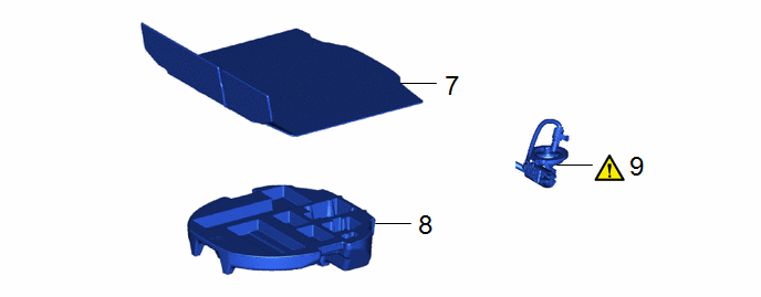
7 |
DECK BOARD ASSEMBLY |
58410B |
- |
- |
- |
|
8 |
SPARE WHEEL CUSHION |
64777J |
- |
- |
- |
|
9 |
SEPARATE REAR TRACTION MOTOR CABLE |
G1149 |
|
- |
- |
|
Procedure |
Part Name Code |
|
|
|
|
|---|---|---|---|---|---|
|
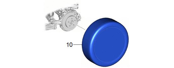
10 |
REAR WHEEL |
- |
- |
- |
- |
|
Procedure |
Part Name Code |
|
|
|
|
|---|---|---|---|---|---|
|
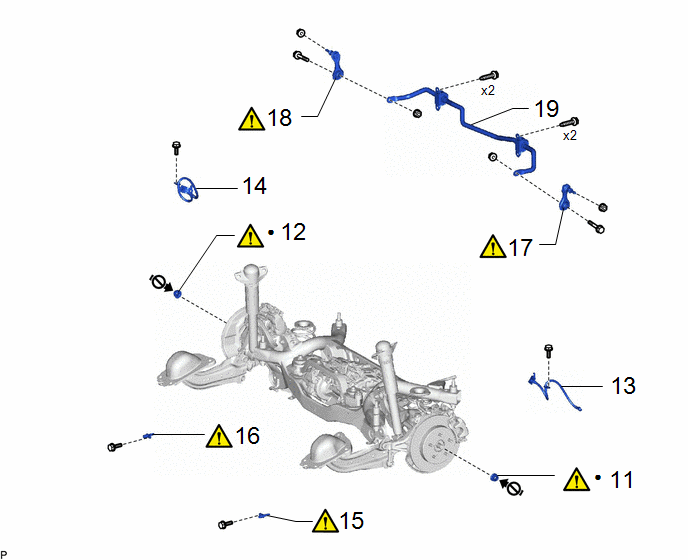
11 |
REAR AXLE SHAFT NUT LH |
42312B |
|
- |
- |
|
12 |
REAR AXLE SHAFT NUT RH |
42311N |
|
- |
- |
|
13 |
REAR FLEXIBLE HOSE LH |
47319F |
- |
- |
- |
|
14 |
REAR FLEXIBLE HOSE RH |
47318F |
- |
- |
- |
|
15 |
REAR SKID CONTROL SENSOR LH |
89544E |
|
- |
- |
|
16 |
REAR SKID CONTROL SENSOR RH |
89544D |
|
- |
- |
|
17 |
REAR STABILIZER LINK ASSEMBLY LH |
48840A |
|
- |
- |
|
18 |
REAR STABILIZER LINK ASSEMBLY RH |
48830D |
|
- |
- |
|
19 |
REAR STABILIZER BAR |
48812 |
- |
- |
- |
|
● |
Non-reusable part |
 |
Do not apply lubricants to the threaded parts |
|
Procedure |
Part Name Code |
|
|
|
|
|---|---|---|---|---|---|
|
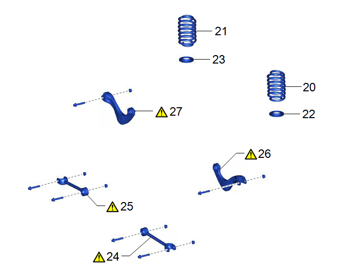
20 |
REAR COIL SPRING LH |
48231B |
- |
- |
- |
|
21 |
REAR COIL SPRING RH |
48231A |
- |
- |
- |
|
22 |
REAR LOWER COIL SPRING INSULATOR LH |
48258C |
- |
- |
- |
|
23 |
REAR LOWER COIL SPRING INSULATOR RH |
48258B |
- |
- |
- |
|
24 |
REAR NO. 1 SUSPENSION ARM ASSEMBLY LH |
48720A |
|
- |
- |
|
25 |
REAR NO. 1 SUSPENSION ARM ASSEMBLY RH |
48710A |
|
- |
- |
|
26 |
SEPARATE REAR UPPER CONTROL ARM ASSEMBLY LH |
48790 |
|
- |
- |
|
27 |
SEPARATE REAR UPPER CONTROL ARM ASSEMBLY RH |
48770A |
|
- |
- |
|
Procedure |
Part Name Code |
|
|
|
|
|---|---|---|---|---|---|
|
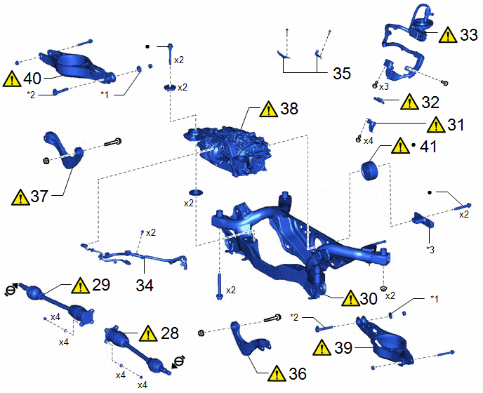
28 |
REAR DRIVE SHAFT ASSEMBLY LH |
42340B |
|
- |
- |
|
29 |
REAR DRIVE SHAFT ASSEMBLY RH |
42330 |
|
- |
- |
|
30 |
REAR SUSPENSION MEMBER SUB-ASSEMBLY |
51206A |
|
- |
- |
|
31 |
CONNECTOR COVER |
82821T |
|
- |
- |
|
32 |
MOTOR CABLE TERMINAL CAP |
G114D |
|
- |
- |
|
33 |
REAR TRACTION MOTOR CABLE |
G1149 |
|
- |
- |
|
34 |
NO. 6 FLOOR WIRE |
82169A |
- |
- |
- |
|
35 |
MOTOR CABLE BRACKET |
- |
- |
- |
- |
|
36 |
REMOVE REAR UPPER CONTROL ARM ASSEMBLY LH |
48790 |
|
- |
- |
|
37 |
REMOVE REAR UPPER CONTROL ARM ASSEMBLY RH |
48770A |
|
- |
- |
|
38 |
REAR TRACTION MOTOR WITH TRANSAXLE ASSEMBLY |
G1050 |
|
- |
- |
|
39 |
REAR NO. 2 SUSPENSION ARM ASSEMBLY LH |
48740F |
|
- |
- |
|
40 |
REAR NO. 2 SUSPENSION ARM ASSEMBLY RH |
48730F |
|
- |
- |
|
41 |
DIFFERENTIAL MOUNT CUSHION |
41651G |
|
- |
- |
|
*1 |
NO. 2 CAMBER ADJUST CAM |
*2 |
REAR SUSPENSION TOE ADJUST CAM SUB-ASSEMBLY |
|
*3 |
DIFFERENTIAL DYNAMIC DAMPER |
- |
- |
|
● |
Non-reusable part |
|
Do not apply lubricants to the threaded parts |
CAUTION / NOTICE / HINT
The necessary procedures (adjustment, calibration, initialization, or registration) that must be performed after parts are removed and installed, or replaced during rear suspension crossmember sub-assembly removal/installation are shown below.
Necessary Procedures After Procedure Performed|
Replaced Part or Performed Procedure |
Necessary Procedure |
Effect/Inoperative Function when Necessary Procedure not Performed |
Link |
|---|---|---|---|
|
Rear wheel alignment adjustment |
|
|
|
|
Suspension, tires, etc. |
Rear television camera assembly optical axis (Back camera position setting) |
Parking Assist Monitor System |
|
|
Initialize headlight ECU subassembly LH |
Automatic headlight beam level control system |
|
|
|
Gas leak from exhaust system is repaired |
Inspection After Repair |
|
|
CAUTION:
- When the engine is hot, do not touch high-temperature areas such as the engine or exhaust pipe.
- Touching high-temperature areas such as the engine and exhaust pipe could result in burns.
.png)
PROCEDURE
1. REMOVE TAIL EXHAUST PIPE ASSEMBLY
Click here .gif)
2. REMOVE MAIN MUFFLER HEAT INSULATOR UPPER
Click here
3. REMOVE SERVICE PLUG GRIP
Click here
4. REMOVE CONNECTOR COVER ASSEMBLY
|
|
Click here |
5. CHECK TERMINAL VOLTAGE
Click here
6. INSTALL CONNECTOR COVER ASSEMBLY
|
|
Click here |
7. REMOVE DECK BOARD ASSEMBLY
Click here
8. REMOVE SPARE WHEEL CUSHION
Click here
9. SEPARATE REAR TRACTION MOTOR CABLE
|
|
Click here |
10. REMOVE REAR WHEEL
Click here
11. REMOVE REAR AXLE SHAFT NUT LH
Click here
12. REMOVE REAR AXLE SHAFT NUT RH
(a) Perform the same procedure as for the LH side.
13. SEPARATE REAR FLEXIBLE HOSE LH
Click here
14. SEPARATE REAR FLEXIBLE HOSE RH
(a) Perform the same procedure as for the LH side.
15. DISCONNECT REAR SKID CONTROL SENSOR LH
Click here
16. DISCONNECT REAR SKID CONTROL SENSOR RH
(a) Perform the same procedure as for the LH side.
17. REMOVE REAR STABILIZER LINK ASSEMBLY LH
Click here
18. REMOVE REAR STABILIZER LINK ASSEMBLY RH
(a) Perform the same procedure as for the LH side.
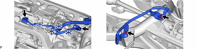
19. REMOVE REAR STABILIZER BAR
Click here
20. REMOVE REAR COIL SPRING LH
Click here
21. REMOVE REAR COIL SPRING RH
(a) Perform the same procedure as for the LH side.
22. REMOVE REAR LOWER COIL SPRING INSULATOR LH
Click here
23. REMOVE REAR LOWER COIL SPRING INSULATOR RH
(a) Perform the same procedure as for the LH side.
24. REMOVE REAR NO. 1 SUSPENSION ARM ASSEMBLY LH
Click here
25. REMOVE REAR NO. 1 SUSPENSION ARM ASSEMBLY RH
(a) Perform the same procedure as for the LH side.
26. SEPARATE REAR UPPER CONTROL ARM ASSEMBLY LH
|
|
NOTICE: Because the nut has its own stopper, do not turn the nut. Loosen the bolt with the nut secured. |

27. SEPARATE REAR UPPER CONTROL ARM ASSEMBLY RH
(a) Perform the same procedure as for the LH side.
28. REMOVE REAR DRIVE SHAFT ASSEMBLY LH
Click here
29. REMOVE REAR DRIVE SHAFT ASSEMBLY RH
(a) Perform the same procedure as for the LH side.
30. REMOVE REAR SUSPENSION MEMBER SUB-ASSEMBLY
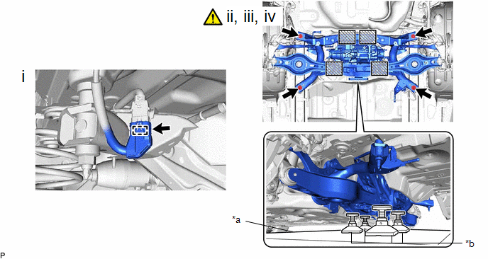
|
*a |
Engine Lifter |
*b |
Attachment |
.png) |
Attachment and Wooden Block Placement Location |
- |
- |
(1) Disconnect the connector.
(2) Using an engine lifter and 4 attachments or equivalent tools, support the rear suspension member sub-assembly as shown in the illustration.
CAUTION:
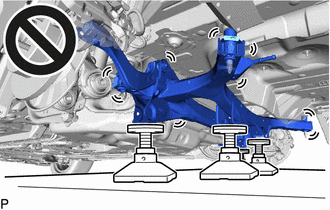
- The rear suspension member sub-assembly is a very heavy component. Make sure that it is supported securely.
- If the rear suspension member sub-assembly is not securely supported, it may drop, resulting in serious injury.
NOTICE:
Use attachments and wooden blocks to keep the rear suspension member sub-assembly level.
(3) Remove the 2 bolts and 2 nuts.
(4) Slowly lower the rear suspension member sub-assembly.
NOTICE:
When lowering the rear suspension member sub-assembly, be careful not to damage the vehicle body or other components installed to the vehicle.
31. REMOVE CONNECTOR COVER
|
|
Click here |
32. REMOVE MOTOR CABLE TERMINAL CAP
|
|
Click here |
33. REMOVE REAR TRACTION MOTOR CABLE
Click here
34. REMOVE NO. 6 FLOOR WIRE
35. REMOVE MOTOR CABLE BRACKET

36. REMOVE REAR UPPER CONTROL ARM ASSEMBLY LH
Click here
37. REMOVE REAR UPPER CONTROL ARM ASSEMBLY RH
(a) Perform the same procedure as for the LH side.
38. REMOVE REAR TRACTION MOTOR WITH TRANSAXLE ASSEMBLY
Click here
39. REMOVE REAR NO. 2 SUSPENSION ARM ASSEMBLY LH
Click here
40. REMOVE REAR NO. 2 SUSPENSION ARM ASSEMBLY RH
(a) Perform the same procedure as for the LH side.
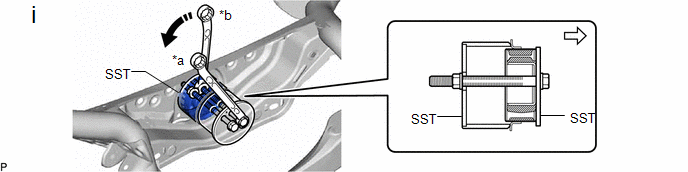
41. REMOVE DIFFERENTIAL MOUNT CUSHION
|
|
NOTICE:
|
|
*a |
Hold |
*b |
Turn |
.png) |
Front of vehicle |
- |
- |
(1) Using SST, remove the differential mount cushion from the rear suspension member sub-assembly.
SST: 09570-48010


