Toyota Corolla Cross: Installation
INSTALLATION
CAUTION / NOTICE / HINT
COMPONENTS (INSTALLATION)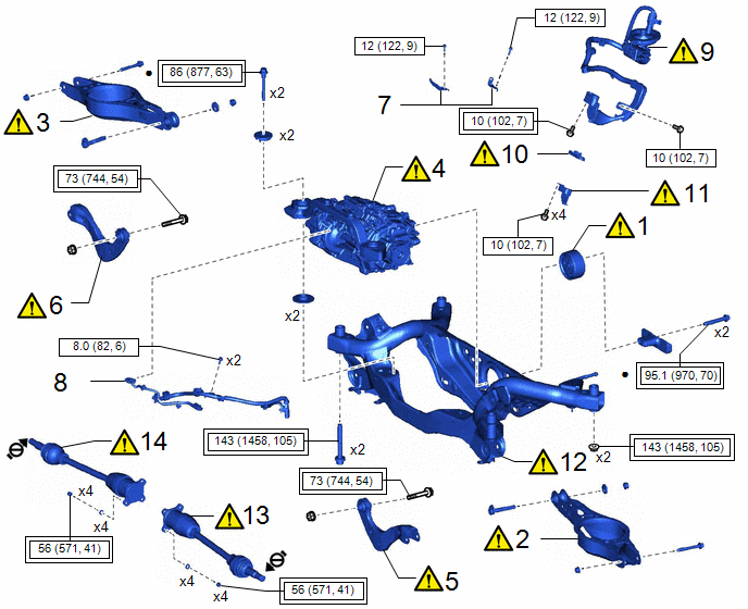
|
Procedure |
Part Name Code |
.png) |
.png) |
.png) |
|
|---|---|---|---|---|---|
|
1 |
DIFFERENTIAL MOUNT CUSHION |
41651G |
|
- |
- |
|
2 |
TEMPORARILY INSTALL REAR NO. 2 SUSPENSION ARM ASSEMBLY LH |
48740F |
|
- |
- |
|
3 |
TEMPORARILY INSTALL REAR NO. 2 SUSPENSION ARM ASSEMBLY LH |
48730F |
|
- |
- |
|
4 |
REAR TRACTION MOTOR WITH TRANSAXLE ASSEMBLY |
G1050 |
|
- |
- |
|
5 |
REAR UPPER CONTROL ARM ASSEMBLY LH |
48790 |
|
- |
- |
|
6 |
REAR UPPER CONTROL ARM ASSEMBLY RH |
48770A |
|
- |
- |
|
7 |
MOTOR CABLE BRACKET |
- |
- |
- |
- |
|
8 |
NO. 6 FLOOR WIRE |
82169A |
- |
- |
- |
|
9 |
REAR TRACTION MOTOR CABLE |
G1149 |
|
- |
- |
|
10 |
MOTOR CABLE TERMINAL CAP |
G114D |
|
- |
- |
|
11 |
CONNECTOR COVER |
82821T |
|
- |
- |
|
12 |
REAR SUSPENSION MEMBER SUB-ASSEMBLY |
51206A |
|
- |
- |
|
13 |
REAR DRIVE SHAFT ASSEMBLY LH |
42340B |
|
- |
- |
|
14 |
REAR DRIVE SHAFT ASSEMBLY RH |
42330 |
|
- |
- |
.png) |
Tightening torque for "Major areas involving basic vehicle performance such as moving/turning/stopping" : N*m (kgf*cm, ft.*lbf) |
.png) |
N*m (kgf*cm, ft.*lbf): Specified torque |
|
● |
Non-reusable part |
.png) |
Do not apply lubricants to the threaded parts |
|
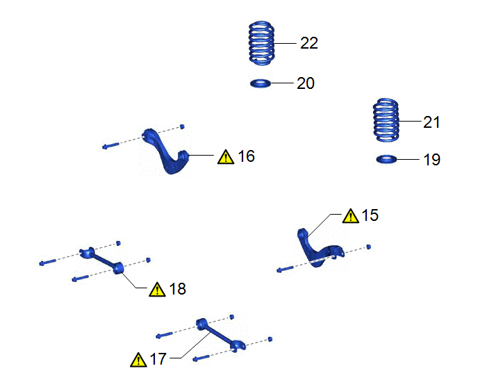
Procedure |
Part Name Code |
|
|
|
|
|---|---|---|---|---|---|
|
15 |
TEMPORARILY INSTALL REAR UPPER CONTROL ARM ASSEMBLY LH |
48790 |
|
- |
- |
|
16 |
TEMPORARILY INSTALL REAR UPPER CONTROL ARM ASSEMBLY RH |
48770A |
|
- |
- |
|
17 |
TEMPORARILY INSTALL REAR NO. 1 SUSPENSION ARM ASSEMBLY LH |
48720A |
|
- |
- |
|
18 |
TEMPORARILY INSTALL REAR NO. 1 SUSPENSION ARM ASSEMBLY RH |
48710A |
|
- |
- |
|
19 |
REAR LOWER COIL SPRING INSULATOR LH |
48258C |
- |
- |
- |
|
20 |
REAR LOWER COIL SPRING INSULATOR RH |
48258B |
- |
- |
- |
|
21 |
REAR COIL SPRING LH |
48231B |
- |
- |
- |
|
22 |
REAR COIL SPRING RH |
48231A |
- |
- |
- |
|
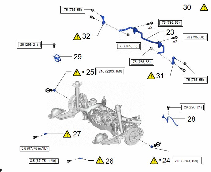
Procedure |
Part Name Code |
|
|
|
|
|---|---|---|---|---|---|
|
23 |
REAR STABILIZER BAR |
48812 |
- |
- |
- |
|
24 |
REAR AXLE SHAFT NUT LH |
42312B |
|
- |
- |
|
25 |
REAR AXLE SHAFT NUT RH |
42311N |
|
- |
- |
|
26 |
REAR SKID CONTROL SENSOR LH |
89544E |
- |
- |
- |
|
27 |
REAR SKID CONTROL SENSOR RH |
89544D |
- |
- |
- |
|
28 |
REAR FLEXIBLE HOSE LH |
47319F |
- |
- |
- |
|
29 |
REAR FLEXIBLE HOSE RH |
47318F |
- |
- |
- |
|
30 |
STABILIZE SUSPENSION |
- |
- |
- |
- |
|
31 |
INSTALL REAR STABILIZER LINK ASSEMBLY LH |
48840A |
- |
- |
- |
|
32 |
INSTALL REAR STABILIZER LINK ASSEMBLY RH |
48830D |
- |
- |
- |
|
|
Tightening torque for "Major areas involving basic vehicle performance such as moving/turning/stopping" : N*m (kgf*cm, ft.*lbf) |
|
N*m (kgf*cm, ft.*lbf): Specified torque |
|
● |
Non-reusable part |
|
Do not apply lubricants to the threaded parts |
|
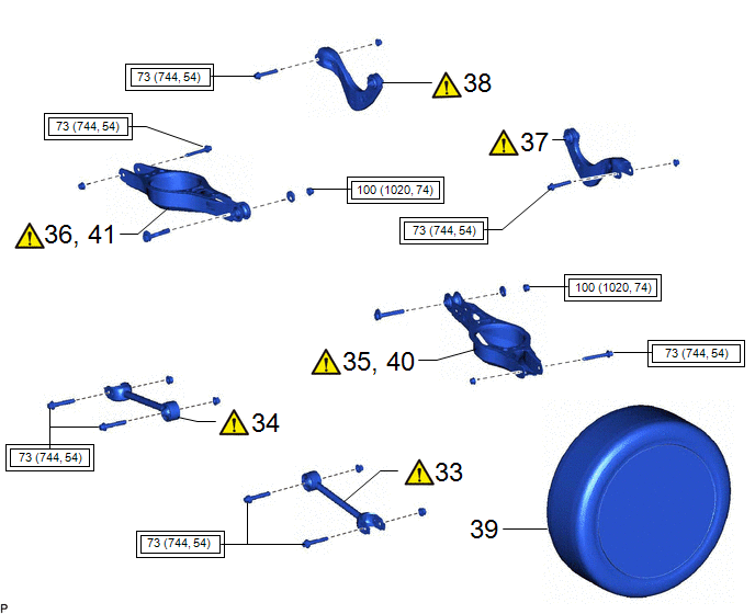
Procedure |
Part Name Code |
|
|
|
|
|---|---|---|---|---|---|
|
33 |
FULLY TIGHTEN REAR NO. 1 SUSPENSION ARM ASSEMBLY LH |
48720A |
|
- |
- |
|
34 |
FULLY TIGHTEN REAR NO. 1 SUSPENSION ARM ASSEMBLY RH |
48710A |
|
- |
- |
|
35 |
FULLY TIGHTEN REAR NO. 2 SUSPENSION ARM ASSEMBLY LH |
48740F |
|
- |
- |
|
36 |
FULLY TIGHTEN REAR NO. 2 SUSPENSION ARM ASSEMBLY RH |
48730F |
|
- |
- |
|
37 |
FULLY TIGHTEN REAR UPPER CONTROL ARM ASSEMBLY LH |
48790 |
|
- |
- |
|
38 |
FULLY TIGHTEN REAR UPPER CONTROL ARM ASSEMBLY RH |
48770A |
|
- |
- |
|
39 |
REAR WHEEL |
- |
- |
- |
- |
|
40 |
FULLY TIGHTEN REAR NO. 2 SUSPENSION ARM ASSEMBLY LH |
48740F |
|
- |
- |
|
41 |
FULLY TIGHTEN REAR NO. 2 SUSPENSION ARM ASSEMBLY RH |
48730F |
|
- |
- |
|
|
Tightening torque for "Major areas involving basic vehicle performance such as moving/turning/stopping" : N*m (kgf*cm, ft.*lbf) |
- |
- |
|
Procedure |
Part Name Code |
|
|
|
|
|---|---|---|---|---|---|
|
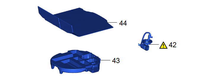
42 |
INSTALL REAR TRACTION MOTOR CABLE |
G1149 |
|
- |
- |
|
43 |
SPARE WHEEL CUSHION |
64777J |
- |
- |
- |
|
44 |
DECK BOARD ASSEMBLY |
58410B |
- |
- |
- |

|
Procedure |
Part Name Code |
|
|
|
|
|---|---|---|---|---|---|
|
45 |
SERVICE PLUG GRIP |
G3834 |
- |
- |
- |

|
Procedure |
Part Name Code |
|
|
|
|
|---|---|---|---|---|---|
|
46 |
UPPER MAIN MUFFLER HEAT INSULATOR |
58327D |
- |
- |
- |
|
|
N*m (kgf*cm, ft.*lbf): Specified torque |
- |
- |
|
Procedure |
Part Name Code |
|
|
|
|
|---|---|---|---|---|---|
|
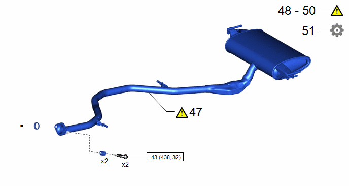
47 |
TAIL EXHAUST PIPE ASSEMBLY |
17430 |
|
- |
- |
|
48 |
INSPECT FOR EXHAUST GAS LEAK |
- |
|
- |
- |
|
49 |
INSPECT AND ADJUST REAR WHEEL ALIGNMENT |
- |
|
- |
- |
|
50 |
CHECK FOR SPEED SENSOR SIGNAL |
- |
|
- |
- |
|
51 |
PERFORM CALIBRATION |
- |
- |
- |
|
|
|
N*m (kgf*cm, ft.*lbf): Specified torque |
● |
Non-reusable part |
PROCEDURE
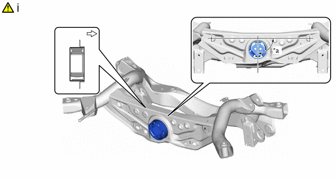
1. INSTALL DIFFERENTIAL MOUNT CUSHION
|
*a |
90° +/- 3° |
- |
- |
.png) |
Front of vehicle |
- |
- |
(1) Temporarily install a new differential mount cushion from the rear of the vehicle as shown in the illustration.
NOTICE:
- Make sure that the rear No. 1 differential mount cushion is aligned within 3° from the center.
- Be sure to install the differential mount cushion in the correct direction.
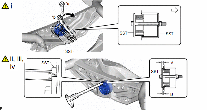
|
*a |
Hold |
*b |
Turn |
|
|
Front of vehicle |
- |
- |
(1) Using SST, press the differential mount cushion into the rear suspension member sub-assembly. (*1)
SST: 09570-48010
(2) Using a vernier caliper, measure the length indicated by (A) in the illustration. (*2)
NOTICE:
- Measure at several points to ensure that the differential mount cushion is pressed in evenly.
- Do not measure on a weld bead.
(3) Repeat the steps *1 and *2 to press the differential mount cushion into the rear suspension member sub-assembly until the length indicated by (A) in the illustration is within the specification.
Reference Length (A):
10.5 to 11.5 mm (0.413 to 0.453 in.)
(4) Remove SST. Using a vernier caliper, measure the differential mount cushion protrusion length indicated by (B) in the illustration and ensure that the measured length is within the specification.
Standard Length (B):
4.5 to 5.5 mm (0.177 to 0.217 in.)
2. TEMPORARILY INSTALL REAR NO. 2 SUSPENSION ARM ASSEMBLY LH
Click here .gif)
3. TEMPORARILY INSTALL REAR NO. 2 SUSPENSION ARM ASSEMBLY LH
(a) Perform the same procedure as for the LH side.
4. INSTALL REAR TRACTION MOTOR WITH TRANSAXLE ASSEMBLY
Click here
5. INSTALL REAR UPPER CONTROL ARM ASSEMBLY LH
Click here
6. INSTALL REAR UPPER CONTROL ARM ASSEMBLY RH
(a) Perform the same procedure as for the LH side.
7. INSTALL MOTOR CABLE BRACKET
Torque:
12 N·m {122 kgf·cm, 9 ft·lbf}
8. INSTALL NO. 6 FLOOR WIRE
Torque:
8.0 N·m {82 kgf·cm, 71 in·lbf}
9. INSTALL REAR TRACTION MOTOR CABLE
Click here
10. INSTALL MOTOR CABLE TERMINAL CAP
|
|
Click here |
11. INSTALL CONNECTOR COVER
|
|
Click here |
12. INSTALL REAR SUSPENSION MEMBER SUB-ASSEMBLY
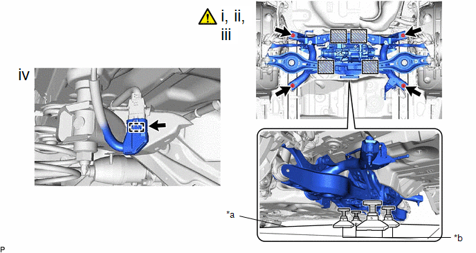
|
*a |
Engine Lifter |
*b |
Attachment |
.png) |
Attachment Placement Location |
- |
- |
(1) Using an engine lifter and 4 attachments or equivalent tools, support the rear suspension member sub-assembly as shown in the illustration.
CAUTION:
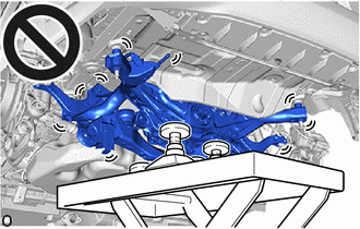
- The rear suspension member sub-assembly is a very heavy component. Make sure that it is supported securely.
- If the rear suspension member sub-assembly is not securely supported, it may drop, resulting in serious injury.
NOTICE:
- Use attachments to keep the rear suspension member sub-assembly level.
- Keep supporting the rear suspension member sub-assembly until the installation has been completed.
(2) Raise the rear suspension member sub-assembly until there is no clearance between the rear suspension member sub-assembly and vehicle body.
(3) Install the rear suspension member sub-assembly with the 2 bolts and 2 nuts.
Torque:
143 N·m {1458 kgf·cm, 105 ft·lbf}
(4) Connect the connector.
13. INSTALL REAR DRIVE SHAFT ASSEMBLY LH
Click here
14. INSTALL REAR DRIVE SHAFT ASSEMBLY RH
(a) Perform the same procedure as for the LH side.
15. TEMPORARILY INSTALL REAR UPPER CONTROL ARM ASSEMBLY LH
|
|
NOTICE:
|
.png)
16. TEMPORARILY INSTALL REAR UPPER CONTROL ARM ASSEMBLY RH
(a) Perform the same procedure as for the LH side.
17. TEMPORARILY INSTALL REAR NO. 1 SUSPENSION ARM ASSEMBLY LH
Click here
18. TEMPORARILY INSTALL REAR NO. 1 SUSPENSION ARM ASSEMBLY RH
(a) Perform the same procedure as for the LH side.
19. INSTALL REAR LOWER COIL SPRING INSULATOR LH
Click here
20. INSTALL REAR LOWER COIL SPRING INSULATOR RH
(a) Perform the same procedure as for the LH side.
21. INSTALL REAR COIL SPRING LH
Click here
22. INSTALL REAR COIL SPRING RH
(a) Perform the same procedure as for the LH side.
23. INSTALL REAR STABILIZER BAR
Click here
24. INSTALL REAR AXLE SHAFT NUT LH
Click here
25. INSTALL REAR AXLE SHAFT NUT RH
(a) Perform the same procedure as for the LH side.
26. CONNECT REAR SKID CONTROL SENSOR LH
Click here
27. CONNECT REAR SKID CONTROL SENSOR RH
(a) Perform the same procedure as for the LH side.
28. INSTALL REAR FLEXIBLE HOSE LH
Click here
29. INSTALL REAR FLEXIBLE HOSE RH
(a) Perform the same procedure as for the LH side.
30. STABILIZE SUSPENSION
Click here
31. INSTALL REAR STABILIZER LINK ASSEMBLY LH
Click here
32. INSTALL REAR STABILIZER LINK ASSEMBLY RH
(a) Perform the same procedure as for the LH side.
33. FULLY TIGHTEN REAR NO. 1 SUSPENSION ARM ASSEMBLY LH
Click here
34. FULLY TIGHTEN REAR NO. 1 SUSPENSION ARM ASSEMBLY RH
(a) Perform the same procedure as for the LH side.
35. FULLY TIGHTEN REAR NO. 2 SUSPENSION ARM ASSEMBLY LH
(a) Install the rear No. 2 suspension arm assembly LH (rear axle carrier sub-assembly side) with the bolt.
Click here
36. FULLY TIGHTEN REAR NO. 2 SUSPENSION ARM ASSEMBLY RH
(a) Perform the same procedure as for the LH side.
37. FULLY TIGHTEN REAR UPPER CONTROL ARM ASSEMBLY LH
(1) Install the rear upper control arm assembly LH (rear axle carrier sub-assembly side) with the bolt.
Torque:
73 N·m {744 kgf·cm, 54 ft·lbf}
NOTICE:
Because the nut has its own stopper, do not turn the nut. Tighten the bolt with the nut secured.
38. FULLY TIGHTEN REAR UPPER CONTROL ARM ASSEMBLY RH
(a) Perform the same procedure as for the LH side.
39. INSTALL REAR WHEEL
Click here
40. FULLY TIGHTEN REAR NO. 2 SUSPENSION ARM ASSEMBLY LH
Click here
41. FULLY TIGHTEN REAR NO. 2 SUSPENSION ARM ASSEMBLY RH
(a) Perform the same procedure as for the LH side.
42. INSTALL REAR TRACTION MOTOR CABLE
|
|
Click here |
43. INSTALL SPARE WHEEL CUSHION
44. INSTALL DECK BOARD ASSEMBLY
45. INSTALL SERVICE PLUG GRIP
Click here
46. INSTALL MAIN MUFFLER UPPER HEAT INSULATOR
Click here
47. INSTALL TAIL EXHAUST PIPE ASSEMBLY
Click here
48. INSPECT FOR EXHAUST GAS LEAK
Click here
49. INSPECT AND ADJUST REAR WHEEL ALIGNMENT
Click here
50. CHECK FOR SPEED SENSOR SIGNAL
Click here
51. PERFORM CALIBRATION
Click here

