Toyota Corolla Cross: Removal
REMOVAL
CAUTION / NOTICE / HINT
COMPONENTS (REOVAL)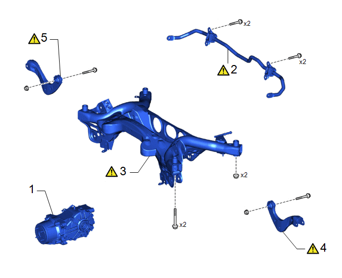
|
Procedure |
Part Name Code |
.png) |
.png) |
.png) |
|
|---|---|---|---|---|---|
|
1 |
REAR DIFFERENTIAL CARRIER SUB-ASSEMBLY |
41101 |
- |
- |
- |
|
2 |
REAR STABILIZER BAR |
48812 |
|
- |
- |
|
3 |
REAR SUSPENSION MEMBER SUB-ASSEMBLY |
51206A |
|
- |
- |
|
4 |
REAR UPPER CONTROL ARM ASSEMBLY LH |
48790 |
|
- |
- |
|
5 |
REAR UPPER CONTROL ARM ASSEMBLY RH |
48770A |
|
- |
- |
|
Procedure |
Part Name Code |
|
|
|
|
|---|---|---|---|---|---|
|
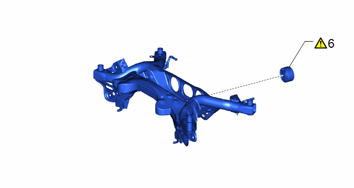
6 |
REAR NO. 1 DIFFERENTIAL MOUNT CUSHION |
41651 |
|
- |
- |
CAUTION / NOTICE / HINT
The necessary procedures (adjustment, calibration, initialization, or registration) that must be performed after parts are removed and installed, or replaced during rear suspension crossmember sub-assembly removal/installation are shown below.
Necessary Procedures After Procedure Performed|
Replaced Part or Performed Procedure |
Necessary Procedure |
Effect/Inoperative Function when Necessary Procedure not Performed |
Link |
|---|---|---|---|
|
Rear wheel alignment adjustment |
|
|
|
|
Dynamic torque control AWD system |
|
|
|
Suspension, tires, etc. |
Rear television camera assembly optical axis (Back camera position setting) |
Parking Assist Monitor System |
|
|
Initialize headlight ECU subassembly LH |
Automatic headlight beam level control system |
|
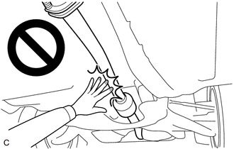
CAUTION:
To prevent burns, do not touch the engine, exhaust pipe or other high temperature components while the engine is hot.
PROCEDURE
1. REMOVE REAR DIFFERENTIAL CARRIER SUB-ASSEMBLY
Click here .gif)
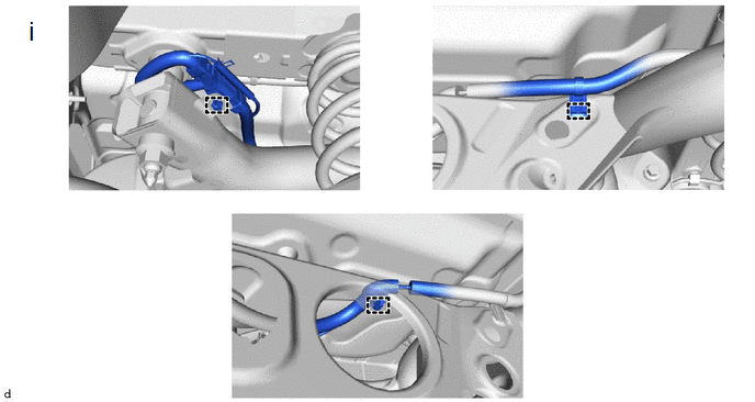
2. REMOVE REAR STABILIZER BAR
|
|
Click here |
3. REMOVE REAR SUSPENSION MEMBER SUB-ASSEMBLY
(1) Disengage the 3clamps to separate the differential carrier wire harness.
|
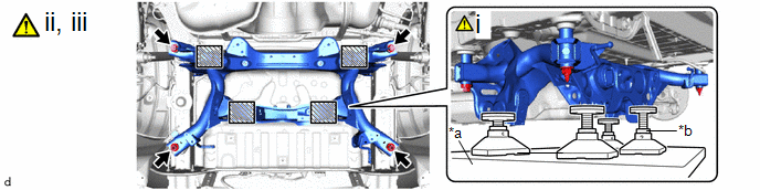
*a |
Engine Lifter |
*b |
Attachment |
.png) |
Attachment and Wooden Block Placement Location |
- |
- |
(1) Using an engine lifter and 4 attachments or equivalent tools, support the rear suspension member sub-assembly as shown in the illustration.
CAUTION:
- The rear suspension member sub-assembly is a very heavy component.
Make sure that it is supported securely.
- If the rear suspension member sub-assembly is not securely supported, it may drop, resulting in serious injury.
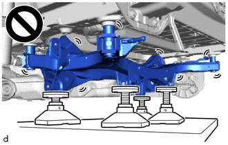
NOTICE:
Use attachments and wooden blocks to keep the rear suspension member sub-assembly level.
(2) Remove the 2 bolts and 2 nuts.
(3) Slowly lower the rear suspension member sub-assembly.
CAUTION:
When lowering the rear suspension member sub-assembly, be careful not to damage the vehicle body or other components installed to the vehicle.
4. REMOVE REAR UPPER CONTROL ARM ASSEMBLY LH
|
|
Click here |
5. REMOVE REAR UPPER CONTROL ARM ASSEMBLY RH
(a) Perform the same procedure as for the LH side.
6. REMOVE REAR NO. 1 DIFFERENTIAL MOUNT CUSHION
|
|
Click here |


