Toyota Corolla Cross: Removal
REMOVAL
CAUTION / NOTICE / HINT
COMPONENTS (REMOVAL)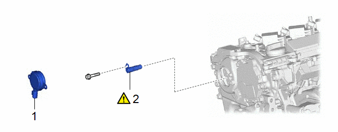
|
Procedure | Part Name Code |
.png) |
.png) |
 |
|---|---|---|---|---|---|
|
1 | CAM TIMING OIL CONTROL SOLENOID ASSEMBLY |
15370 | - |
- | - |
|
2 | CAMSHAFT TIMING OIL CONTROL VALVE ASSEMBLY (EXHAUST CAMSHAFT TIMING GEAR BOLT ASSEMBLY) |
135A0B |
|
- | - |
CAUTION / NOTICE / HINT
NOTICE:
This procedure includes the removal of small-head bolts. Refer to Small-Head Bolts of Basic Repair Hint to identify the small-head bolts.
Click here .gif)
PROCEDURE
1. REMOVE CAM TIMING OIL CONTROL SOLENOID ASSEMBLY
Click here
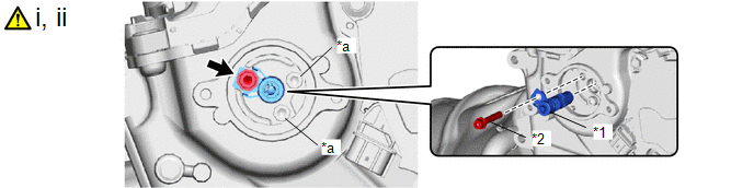
2. REMOVE CAMSHAFT TIMING OIL CONTROL VALVE ASSEMBLY (EXHAUST CAMSHAFT TIMING GEAR BOLT ASSEMBLY)
|
*1 | Camshaft Timing Oil Control Valve Assembly (Exhaust Camshaft Timing Gear Bolt Assembly) |
*2 | Bolt |
|
*a | Do not remove |
- | - |
(1) Using a 5 mm hexagon socket wrench, remove the bolt.
NOTICE:
Do not remove the other 2 bolts.
HINT:
If it is difficult to loosen the bolt due to the tools contacting the vehicle body or other parts, rotate the crankshaft to move the bolt to a position where it can be removed easily.
(2) Remove the camshaft timing oil control valve assembly (exhaust camshaft timing gear bolt assembly) from the camshaft timing exhaust gear assembly.


