Toyota Corolla Cross Owners & Service Manuals

Toyota Corolla Cross: Removal

REMOVAL

CAUTION / NOTICE / HINT

COMPONENTS(REMOVAL)
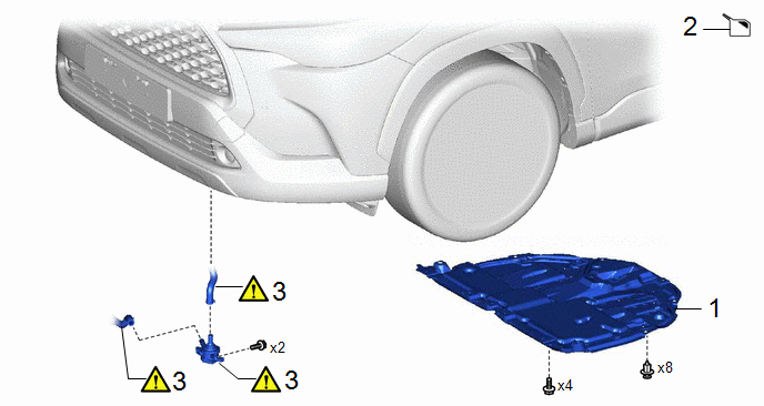
Procedure

Part Name Code

1

NO. 1 ENGINE UNDER COVER ASSEMBLY

51410

-

-

-

2

COOLANT (for Inverter)

-

-

-

3

INVERTER WATER PUMP WITH MOTOR ASSEMBLY

G9040

-

-

PROCEDURE

1. REMOVE NO. 1 ENGINE UNDER COVER ASSEMBLY

Click here

2. DRAIN COOLANT (for Inverter)

Click here

3. REMOVE INVERTER WATER PUMP WITH MOTOR ASSEMBLY

NOTICE:

  • Put pieces of cloth into the pipes and disconnected hoses or cover the pipes and hoses with plastic bags to prevent foreign matter from entering the inverter water pump with motor assembly and inverter cooling system.
  • Do not apply excessive force to the hoses.
  • If the inverter water pump with motor assembly has been struck or dropped, replace it.

*1

Outlet No. 1 Hybrid Water Pump Hose

*2

Inlet Hybrid Water Pump Hose

(1) Disconnect the inverter water pump with motor assembly connector.

NOTICE:

To prevent coolant from entering the inverter water pump with motor assembly connector, perform thefollowing procedure.

Apply insulating tape to the connectors of the wire harness and inverter water pump with motor assembly.

(2) Remove the 2 bolts.

(3) Slide the 2 clips and disconnect the outlet No. 1 hybrid water pump hose and inlet hybrid water pump hose to remove the inverter water pump with motor assembly.

    READ NEXT:

     Installation

    INSTALLATION CAUTION / NOTICE / HINT COMPONENTS(INSTALLATION) Procedure Part Name Code 1 INVERTER WATER PUMP WITH MOTOR ASSEMBLY G9040

     M20a-fks (cooling)

     Coolant

    ComponentsCOMPONENTS ILLUSTRATION *1 RESERVE TANK CAP *2 RADIATOR DRAIN COCK PLUG *3 NO. 1 ENGINE UNDER COVER ASSEMBLY - - N*m (kgf*cm, ft.*lbf): S

    SEE MORE:

     Problem Symptoms Table

    PROBLEM SYMPTOMS TABLE HINT: Use the table below to help determine the cause of problem symptoms. If multiple suspected areas are listed, the potential causes of the symptoms are listed in order of probability in the "Suspected Area" column of the table. Check each symptom by

     System Diagram

    SYSTEM DIAGRAM HINT: See the layout drawing to confirm the locations and tightening torque of flexible hoses and brake lines. *A for HEV Model - - *1 Brake Master Cylinder Sub-assembly *2 Brake Boost

    © 2020-2024 Copyright www.tcorollacross.com