Toyota Corolla Cross: Removal
REMOVAL
CAUTION / NOTICE / HINT
COMPONENTS (REOVAL)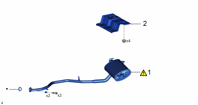
|
Procedure |
Part Name Code |
.png) |
.png) |
.png) |
|
|---|---|---|---|---|---|
|
1 |
TAIL EXHAUST PIPE ASSEMBLY |
17430 |
|
- |
- |
|
2 |
MAIN MUFFLER UPPER HEAT INSULATOR |
58327D |
- |
- |
- |
|
● |
Non-reusable part |
- |
- |
|
Procedure |
Part Name Code |
|
|
|
|
|---|---|---|---|---|---|
|
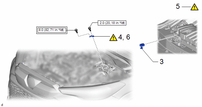
3 |
SERVICE PLUG GRIP |
G3834 |
- |
- |
- |
|
4 |
REMOVE CONNECTOR COVER ASSEMBLY |
- |
|
- |
- |
|
5 |
CHECK TERMINAL VOLTAGE |
- |
|
- |
- |
|
6 |
INSTALL CONNECTOR COVER ASSEMBLY |
- |
|
- |
- |
.png) |
Tightening torque for "Major areas involving basic vehicle performance such as moving/turning/stopping" : N*m (kgf*cm, ft.*lbf) |
.png) |
N*m (kgf*cm, ft.*lbf): Specified torque |

|
Procedure |
Part Name Code |
|
|
|
|
|---|---|---|---|---|---|
|
7 |
DECK BOARD ASSEMBLY |
58410B |
- |
- |
- |
|
8 |
SPARE WHEEL CUSHION |
64777J |
- |
- |
- |
|
Procedure |
Part Name Code |
|
|
|
|
|---|---|---|---|---|---|
|
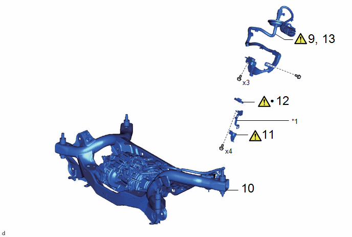
9 |
SEPARATE REAR TRACTION MOTOR CABLE |
G1149 |
|
- |
- |
|
10 |
REAR SUSPENSION MEMBER SUB-ASSEMBLY |
51206A |
- |
- |
- |
|
11 |
CONNECTOR COVER |
82821T |
|
- |
- |
|
12 |
MOTOR CABLE TERMINAL CAP |
G114D |
|
- |
- |
|
13 |
REMOVE REAR TRACTION MOTOR CABLE |
G1149 |
|
- |
- |
|
*1 |
CONNECTOR COVER BRACKET |
- |
- |
|
● |
Non-reusable part |
- |
- |
CAUTION / NOTICE / HINT
The necessary procedures (adjustment, calibration, initialization, or registration) that must be performed after parts are removed and installed, or replaced during rear traction motor cable removal/installation are shown below.
Necessary Procedures After Parts Removed/Installed/Replaced|
Replaced Part or Performed Procedure |
Necessary Procedures |
Effect/Inoperative Function when Necessary Procedure not Performed |
Link |
|---|---|---|---|
|
Replacement of rear traction motor with transaxle assembly |
Resolver learning |
|
|
|
Rear wheel alignment adjustment |
|
|
|
CAUTION:
- Orange wire harnesses and connectors indicate high-voltage circuits. To
prevent electric shock, always follow the procedure described in the repair
manual.
.png)
Click here
.gif)
- To prevent electric shock, wear insulated gloves when working on wire harnesses
and components of the high voltage system.
.png)
HINT:
When the cable is disconnected/reconnected to the auxiliary battery terminal, systems temporarily stop operating. However, each system has a function that completes learning the first time the system is used.
- Learning completes when vehicle is driven
Effect/Inoperative Function When Necessary Procedures are not Performed
Necessary Procedures
Link
Front Camera System
Drive the vehicle straight ahead at 15 km/h (10 mph) or more for 5 second or more.
- Learning completes when vehicle is operated normally
Effect/Inoperative Function When Necessary Procedures are not Performed
Necessary Procedures
Link
Power door lock control system
- Back door opener
Perform door unlock operation with door control switch or electrical key transmitter sub-assembly switch.
Power back door system
Fully close the back door by hand.
HINT:
Initialization is not necessary if the above procedures are performed while the back door is closed.
Air conditioning system
After the ignition switch is turned to ON, the servo motor standard position is recognized.
-
PROCEDURE
1. REMOVE TAIL EXHAUST PIPE ASSEMBLY
|
|
Click here |
2. REMOVE MAIN MUFFLER UPPER HEAT INSULATOR

3. REMOVE SERVICE PLUG GRIP
Click here
4. REMOVE CONNECTOR COVER ASSEMBLY
|
|
Click here |
5. CHECK TERMINAL VOLTAGE
Click here
6. INSTALL CONNECTOR COVER ASSEMBLY
|
|
Click here |
7. REMOVE DECK BOARD ASSEMBLY
Click here
8. REMOVE SPARE WHEEL CUSHION
Click here
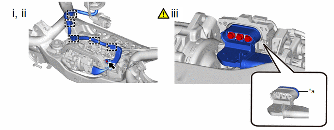
9. SEPARATE REAR TRACTION MOTOR CABLE
|
|
CAUTION: Be sure to wear insulated gloves. |

(1) Disengage the claw and raise the lock lever to disconnect the connector as shown in the illustration.
(2) Disconnect the connector.
(3) Disengage the clamp to separate the rear traction motor cable.
(4) Disengage the clamp to separate the rear traction motor cable.
(5) Remove the grommet and pull out the rear traction motor cable to the outside of the vehicle.
10. REMOVE REAR SUSPENSION MEMBER SUB-ASSEMBLY
Click here
11. REMOVE CONNECTOR COVER
|
|
CAUTION: Be sure to wear insulated gloves. |
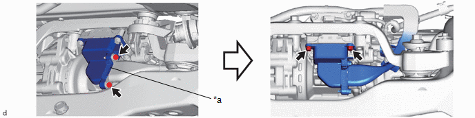
|
*a |
CONNECTOR COVER BRACKET |
- |
- |
12. REMOVE MOTOR CABLE TERMINAL CAP
|
|
CAUTION: Be sure to wear insulated gloves. |

13. REMOVE REAR TRACTION MOTOR CABLE
|
|
CAUTION: Be sure to wear insulated gloves. |
|
*a |
Waterproof Seal |
- |
- |
(1) Disengage the 5 clamps to separate the rear traction motor cable.
(2) Remove the bolt to separate the rear traction motor cable.
(3) Using an insulated tool, remove the 3 bolts and disconnect the rear traction motor cable from the rear traction motor with transaxle assembly.
NOTICE:
- Keep the rear traction motor cable and their installation area free from foreign matter, water, etc.
- Do not touch the waterproof seal or terminals of the rear traction motor cable.
- Cover the hole where the rear traction motor cable was connected with tape (non-residue type) or equivalent to prevent entry of foreign matter.


