Toyota Corolla Cross: Removal
REMOVAL
CAUTION / NOTICE / HINT
COMPONENTS (REMOVAL)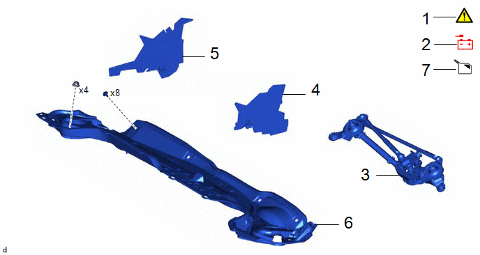
|
Procedure |
Part Name Code |
.png) |
.png) |
.png) |
|
|---|---|---|---|---|---|
|
1 |
PRECAUTION |
- |
- |
- |
- |
|
2 |
DISCONNECT CABLE FROM NEGATIVE AUXILIARY BATTERY TERMINAL |
- |
- |
- |
- |
|
3 |
WINDSHIELD WIPER MOTOR AND LINK ASSEMBLY |
- |
- |
- |
- |
|
4 |
WATER GUARD PLATE |
55734D |
- |
- |
- |
|
5 |
NO. 1 HEATER AIR DUCT SPLASH SHIELD SEAL |
55737B |
- |
- |
- |
|
6 |
OUTER COWL TOP PANEL SUB-ASSEMBLY |
55701J |
- |
- |
- |
|
7 |
DRAIN BRAKE FLUID |
- |
- |
|
- |
|
Procedure |
Part Name Code |
|
|
|
|
|---|---|---|---|---|---|
|
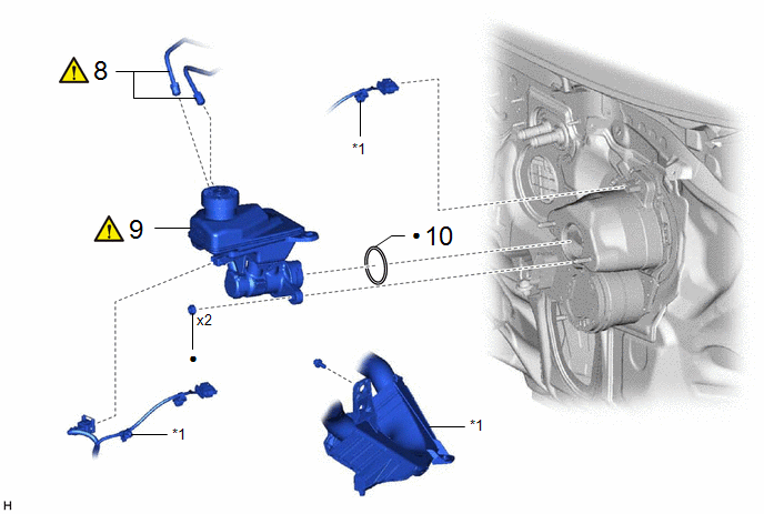
8 |
DISCONNECT BRAKE LINE |
- |
|
- |
- |
|
9 |
BRAKE MASTER CYLINDER SUB-ASSEMBLY |
47201 |
|
- |
- |
|
10 |
BRAKE MASTER CYLINDER O-RING |
- |
- |
- |
- |
|
*1 |
ENGINE ROOM MAIN WIRE |
- |
- |
|
● |
Non-reusable part |
- |
- |
CAUTION / NOTICE / HINT
The necessary procedures (adjustment, calibration, initialization, or registration) that must be performed after parts are removed and installed, or replaced during the brake master cylinder sub-assembly removal/installation are shown below.
HINT:
When the cable is disconnected/reconnected to the auxiliary battery terminal, systems temporarily stop operating. However, each system has a function that completes learning the first time the system is used.
- Learning completes when vehicle is driven
Effect/Inoperative Function When Necessary Procedures are not Performed
Necessary Procedures
Link
Front camera system
Drive the vehicle straight ahead at 15 km/h (10 mph) or more for 1 second or more.
.gif)
- Learning completes when vehicle is operated normally
Effect/Inoperative Function When Necessary Procedures are not Performed
Necessary Procedures
Link
Power door lock control system
- Back door opener
Perform door unlock operation with door control switch or electrical key transmitter sub-assembly switch.
Power back door system
Fully close the back door by hand.
HINT:
Initialization is not necessary if the above procedures are performed while the back door is closed.
Air conditioning system
After the ignition switch is turned to ON, the servo motor standard position is recognized.
-
PROCEDURE
1. PRECAUTION
|
|
NOTICE: After the ignition switch is turned off, there may be a waiting time before disconnecting the negative (-) auxiliary battery terminal. Click here |
2. DISCONNECT CABLE FROM NEGATIVE AUXILIARY BATTERY TERMINAL
Click here
3. REMOVE WINDSHIELD WIPER MOTOR AND LINK ASSEMBLY
Click here
4. REMOVE WATER GUARD PLATE
Click here
5. REMOVE NO. 1 HEATER AIR DUCT SPLASH SHIELD SEAL
Click here
6. REMOVE OUTER COWL TOP PANEL SUB-ASSEMBLY
Click here
7. DRAIN BRAKE FLUID
|
|
NOTICE: If brake fluid leaks onto any painted surface, immediately wash it off. |
8. DISCONNECT BRAKE LINE
|
|
NOTICE:
|

(1) Using a union nut wrench, disconnect the 2 brake lines from the brake master cylinder sub-assembly.
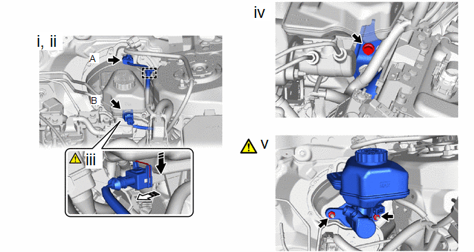
9. REMOVE BRAKE MASTER CYLINDER SUB-ASSEMBLY
.png) |
Push in this direction |
.png) |
Disconnect the connector in this direction |
(1) Disconnect the connector (A) from the brake booster.
(2) Disengage the clamp from the brake master cylinder reservoir assembly.
(3) Disconnect the connector (B) from the brake master cylinder reservoir assembly as shown in the illustration.
(4) Remove the bolt to separate the engine room main wire from the vehicle body.
(5) Remove the 2 nuts and brake master cylinder sub-assembly from the brake booster assembly.
NOTICE:
- The brake master cylinder sub-assembly requires careful handling. Do not drop or subject the brake master cylinder sub-assembly to any impact. Do not reuse a brake master cylinder sub-assembly that has been dropped.
- Do not hold the brake master cylinder sub-assembly by the master cylinder piston. Hold the brake master cylinder sub-assembly by its body or its reservoir when carrying it.
- Do not pull out the master cylinder piston.
- Do not strike or pinch the master cylinder piston, or cause any damage to the master cylinder piston by any other means.
- When installing the brake master cylinder sub-assembly to the brake booster assembly, or when removing the brake master cylinder sub-assembly from the brake booster assembly, make sure that the brake master cylinder sub-assembly is kept horizontal or with its tip facing downward (the master cylinder piston is facing upward) to prevent the master cylinder piston from falling out.
- Do not allow any foreign matter to contaminate the master cylinder piston. If any foreign matter gets on the master cylinder piston, remove it by using a piece of new and dry cloth. Do not use water or detergent. Then apply an even layer of lithium soap base glycol grease around the circumference (sliding part) of the master cylinder piston.
- Do not use any other types of grease.
10. REMOVE BRAKE MASTER CYLINDER O-RING