Toyota Corolla Cross Owners & Service Manuals

Toyota Corolla Cross: Removal

REMOVAL

CAUTION / NOTICE / HINT

COMPONENTS (REMOVAL)
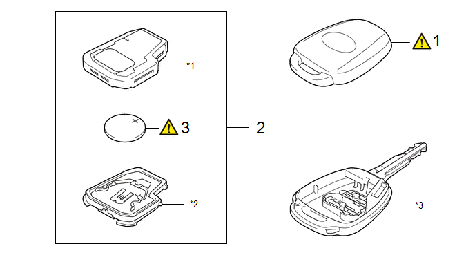
Procedure

Part Name Code

1

TRANSMITTER HOUSING COVER

89751A

-

-

2

DOOR CONTROL TRANSMITTER SUB-ASSEMBLY

89071C

-

-

-

3

TRANSMITTER BATTERY

89745A

-

-

*1

TRANSMITTER BATTERY COVER

*2

TRANSMITTER BATTERY CASE

*3

TRANSMITTER HOUSING CASE

-

-

CAUTION / NOTICE / HINT

The necessary procedures (adjustment, calibration, initialization or registration) that must be performed after parts are removed and installed, or replaced during door control transmitter assembly removal/installation are shown below.

Necessary Procedures After Parts Removed/Installed/Replaced

Replaced Part or Performed Procedure

Necessary Procedure

Effect/Inoperative Function when Necessary Procedure not Performed

Link

Door control transmitter assembly

Code registration

Register a new recognition code

Register a new recognition code

Wireless door lock control system (w/o Smart Key System)

PROCEDURE

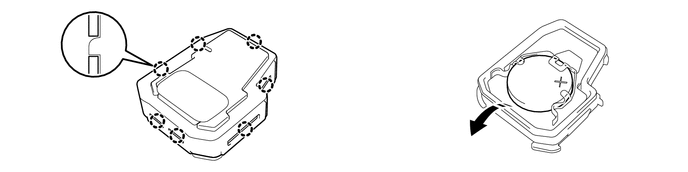
1. REMOVE TRANSMITTER HOUSING COVER

Click here

2. REMOVE DOOR CONTROL TRANSMITTER SUB-ASSEMBLY

Click here

3. REMOVE TRANSMITTER BATTERY

NOTICE:

  • Do not push the terminals with your finger.
  • Do not forcibly pry up the transmitter battery as the terminals may be damaged.
  • Do not touch the transmitter battery with wet hands. Moisture may cause rust.
  • Do not touch or move any components inside the transmitter housing case. It may interfere with proper operation.
  • When replacing the transmitter battery, before starting work, remove static electricity that has built up in the body by touching, for example, the vehicle to prevent the electrical key transmitter sub-assembly from being damaged.

Remove in this Direction

-

-

    READ NEXT:

     Installation

    INSTALLATION CAUTION / NOTICE / HINT COMPONENTS (INSTALLATION) Procedure Part Name Code 1 TRANSMITTER BATTERY

     Setup

     Customize Parameters

    Procedure PROCEDURE PROCEDURE 1. CUSTOMIZE INTUITIVE PARKING ASSIST SYSTEM Click here 2. CUSTOMIZE PARKING SUPPORT BRAKE SYSTEM Click here 3. CUSTOMIZE BLIND SPOT MONITOR SYSTEM Click he

    SEE MORE:

     Terminals Of Ecu

    TERMINALS OF ECU CLEARANCE WARNING ECU ASSEMBLY (a) Disconnect the I24 clearance warning ECU assembly connector. (b) Measure the voltage and resistance on the wire harness side connector according to the value(s) in the table below. Terminal No. (Symbol) Terminal Descri

     Vehicle load limits

    Vehicle load limits include total load capacity, seating capacity, towing capacity and cargo capacity. Total load capacity (vehicle capacity weight) Total load capacity means the combined weight of occupants, cargo and luggage. Seating capacity Seating capacity means the maximum number of o

    © 2020-2024 Copyright www.tcorollacross.com