Toyota Corolla Cross: Inspection
INSPECTION
PROCEDURE
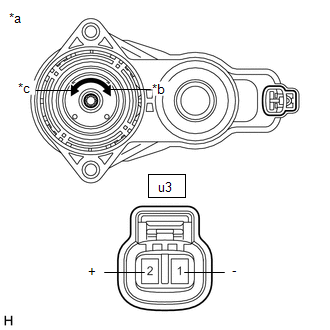
1. INSPECT PARKING BRAKE ACTUATOR ASSEMBLY LH
(a) Parking brake actuator assembly LH operation inspection
|
(1) Apply voltage to the terminals of the parking brake actuator
assembly LH and check that it operates as specified.
OK:
|
Tester Connection
|
Specified Condition
|
|
Auxiliary battery positive (+) - u3-2 (+)
Auxiliary battery negative (-) - u3-1 (-)
|
Lock
|
|
Auxiliary battery positive (+) - u3-1 (-)
Auxiliary battery negative (-) - u3-2 (+)
|
Release
|
|
 |
|
*a
|
Component without harness connected
(Parking Brake Actuator Assembly LH)
|
|
*b
|
Lock
|
|
*c
|
Release
|
|
|
(2) If the result is not as specified, replace the parking brake actuator
assembly LH.
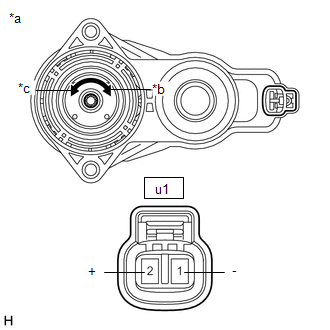
2. INSPECT PARKING BRAKE ACTUATOR ASSEMBLY RH
(a) Parking brake actuator assembly RH operation inspection
|
(1) Apply voltage to the terminals of the parking brake actuator
assembly RH and check that it operates as specified.
OK:
|
Tester Connection
|
Specified Condition
|
|
Auxiliary battery positive (+) - u1-2 (+)
Auxiliary battery negative (-) - u1-1 (-)
|
Lock
|
|
Auxiliary battery positive (+) - u1-1 (-)
Auxiliary battery negative (-) - u1-2 (+)
|
Release
|
|
 |
|
*a
|
Component without harness connected
(Parking Brake Actuator Assembly RH)
|
|
*b
|
Lock
|
|
*c
|
Release
|
|
|
(2) If the result is not as specified, replace the parking brake actuator
assembly RH.
READ NEXT:
INSTALLATION
CAUTION / NOTICE / HINT
COMPONENTS (INSTALLATION)
Procedure
Part Name Code
1
PARKING BRAKE ACTUATOR ASSEMB
REMOVAL
CAUTION / NOTICE / HINT
COMPONENTS (REMOVAL)
Procedure
Part Name Code
1
POSITION INDICATOR HOUSING ASSEMBLY
SEE MORE:
DESCRIPTION
DTC No. Detection Item
DTC Detection Condition Trouble Area
Warning Indicate Test Mode / Check Mode
B001011 Passenger Frontal Stage 1 Deployment Control Circuit Short to Ground
One of the following conditions is met:
The airbag ECU assembly
DESCRIPTION
Refer to DTC P091412.
Click here
DTC No.
Detection Item
DTC Detection Condition
Trouble Area
MIL
Memory
Note
P091414
Gear Shift Position Circuit Short to Ground or Open


