Toyota Corolla Cross: Relay
On-vehicle Inspection
ON-VEHICLE INSPECTION
PROCEDURE
1. INSPECT NO. 1 ELECTRONIC FUEL INJECTION MAIN RELAY (EFI-MAIN NO. 1)
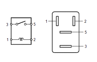
| (a) Measure the resistance according to the value(s) in the table below.
Standard Resistance: |
Tester Connection | Condition |
Specified Condition | |
3 - 5 | Auxiliary battery voltage not applied between terminals 1 and 2 |
10 kΩ or higher | |
Auxiliary battery voltage applied between terminals 1 and 2 |
Below 1 Ω | If the result is not as specified, replace the No. 1 electronic fuel injection main relay (EFI-MAIN NO. 1). |
|
2. INSPECT NO. 3 ELECTRONIC FUEL INJECTION MAIN RELAY (EFI-MAIN NO. 3)
| (a) Measure the resistance according to the value(s) in the table below.
Standard Resistance: |
Tester Connection | Condition |
Specified Condition | |
3 - 5 | Auxiliary battery voltage not applied between terminals 1 and 2 |
10 kΩ or higher | |
Auxiliary battery voltage applied between terminals 1 and 2 |
Below 1 Ω | If the result is not as specified, replace the No. 3 electronic fuel injection main relay (EFI-MAIN NO. 3). |
|
3. INSPECT INJECTOR RELAY (D INJ)
| (a) Measure the resistance according to the value(s) in the table below.
Standard Resistance: |
Tester Connection | Condition |
Specified Condition | |
3 - 5 | Auxiliary battery voltage not applied between terminals 1 and 2 |
10 kΩ or higher | |
Auxiliary battery voltage applied between terminals 1 and 2 |
Below 1 Ω | If the result is not as specified, replace the injector relay (D INJ). |
|
4. INSPECT VVT RELAY (VVT)
| (a) Measure the resistance according to the value(s) in the table below.
Standard Resistance: |
Tester Connection | Condition |
Specified Condition | |
3 - 5 | Auxiliary battery voltage not applied between terminals 1 and 2 |
10 kΩ or higher | |
Auxiliary battery voltage applied between terminals 1 and 2 |
Below 1 Ω | If the result is not as specified, replace the VVT relay (VVT). |
|
READ NEXT:
PRECAUTION WHEN USING GTS
CAUTION:
Strictly obey all traffic rules and regulations.
Do not drive the vehicle with the GTS cable contacting the pedals, shift lever or steering wheel.
Dr
DEFINITION OF TERMS
Term Definition
Monitor Description Description of what the ECM monitors and how it detects malfunctions (monitoring purpose and details).
Related DTCs
SEE MORE:
DESCRIPTION The cooler thermistor (room temperature sensor) is installed in the instrument panel to detect the cabin temperature, which is used to control the air conditioning system. The resistance of the cooler thermistor (room temperature sensor) changes in accordance with the cabin temperature.
DIAGNOSIS SYSTEM
DLC3 (Data Link Connector 3)
(a) Check the DLC3.
Click here
AUXILIARY BATTERY VOLTAGE
Standard Voltage:
Switch Condition
Specified Condition
Ignition switch ON
11 to 14 V
If the voltage is below 11 V, replace or