Toyota Corolla Cross: Reassembly
REASSEMBLY
CAUTION / NOTICE / HINT
COMPONENTS (REASSEMBLY)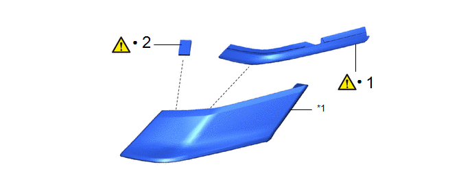
|
Procedure | Part Name Code |
.png) |
.png) |
 |
|---|---|---|---|---|---|
|
1 | FRONT PILLAR COVER PROTECTOR |
61992 |
|
- | - |
|
2 | NO. 1 MOULDING TAPE |
75895A |
|
- | - |
.gif)
|
*1 | FRONT PILLAR UPPER COVER |
- | - |
|
● | Non-reusable part |
- | - |
CAUTION / NOTICE / HINT
HINT:
- Use the same procedure for the RH side and LH side.
- The following procedure is for the LH side.
PROCEDURE
1. INSTALL FRONT PILLAR COVER PROTECTOR
|
|
NOTICE: When installing a new front pillar cover protector, heat the front pillar upper cover using a heat light. |
Standard:
|
Item | Temperature |
|---|---|
|
Front Pillar Upper Cover |
20 to 30°C (68 to 86°F) |
CAUTION:
- Do not touch the heat light and heated parts.
- Touching the heat light may result in burns.
- Touching heated parts for a long time may result in burns.
.png)
|
*a | Heated Part |
|
*b | Heat Light |
NOTICE:
Do not heat the front pillar upper cover excessively.
|
*a | Location Line |
- | - |
(1) Clean the front pillar upper cover.
1. Using a heat light, heat the front pillar upper cover surface.
2. Remove any remaining double-sided tape from the front pillar upper cover.
3. Wipe off any tape adhesive residue with cleaner.
NOTICE:
- Installing the front pillar cover protector with some double-sided tape remaining may cause poor adhesion. Perform this procedure until the tape is sufficiently removed.
- Make sure to use a cloth when removing. Using a screwdriver, etc., may cause damage and poor adhesion.
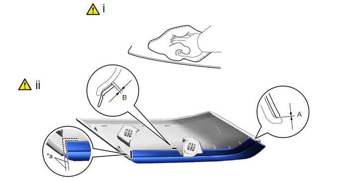
(2) Install a new front pillar cover protector.
1. Using a heat light, heat the front pillar upper cover.
2. Remove the release paper from the front pillar cover protector.
HINT:
After removing the release paper, keep the exposed adhesive free from foreign matter.
3. Install the front pillar cover protector as shown in the illustration.
Standard Measurement:
|
Area | Measurement |
Area | Measurement |
|---|---|---|---|
|
A | 0 mm (0 in.) |
B | 1.0 mm (0.0394 in.) |
HINT:
- Make sure that the end of the front pillar cover protector is between the location line.
- Press the front pillar cover protector firmly to install it.
2. INSTALL NO. 1 MOULDING TAPE
|
|
NOTICE: When installing a new No. 1 moulding tape, heat the front pillar upper cover using a heat light. |
Standard:
|
Item | Temperature |
|---|---|
|
Front Pillar Upper Cover |
20 to 30°C (68 to 86°F) |
CAUTION:
- Do not touch the heat light and heated parts.
- Touching the heat light may result in burns.
- Touching heated parts for a long time may result in burns.
|
*a | Heated Part |
|
*b | Heat Light |
NOTICE:
Do not heat the front pillar upper cover excessively.
|
*a | Location Line |
- | - |
(1) Clean the front pillar upper cover.
1. Using a heat light, heat the front pillar upper cover surface.
2. Remove any remaining double-sided tape from the front pillar upper cover.
3. Wipe off any tape adhesive residue with cleaner.
NOTICE:
- Installing the No. 1 moulding tape with some double-sided tape remaining may cause poor adhesion. Perform this procedure until the tape is sufficiently removed.
- Make sure to use a cloth when removing. Using a screwdriver, etc., may cause damage and poor adhesion.
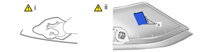
(2) Install a new No. 1 moulding tape.
1. Using a heat light, heat the front pillar upper cover.
2. Remove the release paper from the No. 1 moulding tape.
HINT:
After removing the release paper, keep the exposed adhesive free from foreign matter.
3. Install the No. 1 moulding tape as shown in the illustration.
HINT:
- Install the No. 1 moulding tape along the location line on the front pillar upper cover.
- Press the No. 1 moulding tape firmly to install it.


