Toyota Corolla Cross: Reassembly
REASSEMBLY
CAUTION / NOTICE / HINT
COMPONENTS (REASSEMBLY)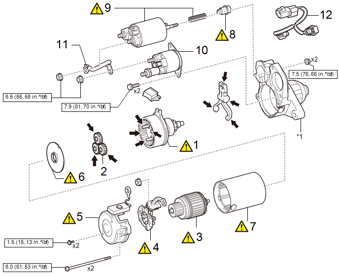
|
Procedure | Part Name Code |
.png) |
.png) |
 |
|---|---|---|---|---|---|
|
1 | STARTER CENTER BEARING CLUTCH SUB-ASSEMBLY |
28021 |
|
- | - |
|
2 | PLANETARY GEAR |
- | - |
- | - |
|
3 | STARTER ARMATURE ASSEMBLY |
28160 |
|
- | - |
|
4 | STARTER BRUSH HOLDER ASSEMBLY |
28140 |
|
- | - |
|
5 | STARTER COMMUTATOR END FRAME ASSEMBLY |
- |
|
- | - |
|
6 | STARTER ARMATURE PLATE |
- |
|
- | - |
|
7 | STARTER YOKE ASSEMBLY |
28120 |
|
- | - |
|
8 | PLUNGER |
- |
|
- | - |
|
9 | REPAIR SERVICE STARTER KIT |
28226B |
|
- | - |
|
10 | STARTER INRUSH CURRENT REDUCTION RELAY |
28249 | - |
- | - |
|
11 | WIRE HARNESS |
- | - |
- | - |
|
12 | HARNESS |
- | - |
- | - |
.gif)
|
*1 | STARTER DRIVE HOUSING ASSEMBLY |
- | - |
.png) |
N*m (kgf*cm, ft.*lbf): Specified torque |
.png) |
High-temperature grease |
PROCEDURE
1. INSTALL STARTER CENTER BEARING CLUTCH SUB-ASSEMBLY

|
*1 | Starter Center Bearing Clutch Sub-assembly |
*2 | Pinion Drive Lever |
|
*3 | Rubber Seal |
*4 | Starter Drive Housing Assembly |
|
|
High-temperature Grease |
- | - |
(1) Apply high-temperature grease to the pinion drive lever as shown in the illustration.
(2) Install the pinion drive lever and rubber seal to the starter center bearing clutch sub-assembly.
(3) Install the starter center bearing clutch sub-assembly together with pinion drive lever and rubber seal to the starter drive housing assembly.
2. INSTALL PLANETARY GEAR

|
|
High-temperature Grease | - |
- |
3. INSTALL STARTER ARMATURE ASSEMBLY
|
|
NOTICE: The magnet of the starter yoke assembly may attract the starter armature assembly when the starter armature assembly is installed, causing the magnet to break. |

|
*1 | Starter Yoke Assembly |
*2 | Starter Armature Assembly |
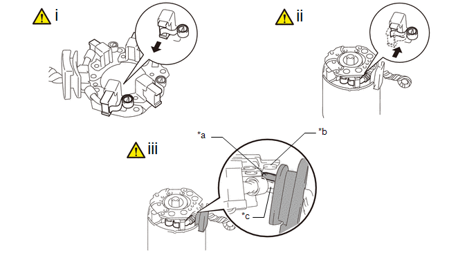
4. INSTALL STARTER BRUSH HOLDER ASSEMBLY
|
*a | Grommet |
*b | Negative (-) Brush Holder Plate |
|
*c | Positive (+) Motor Lead Wire |
- | - |
(1) Hold the brush spring back and set the 4 brushes as shown in the illustration.
(2) Install the starter brush holder assembly to the starter armature assembly and push in the 4 brushes as shown in the illustration.
(3) Fit the protrusion of the grommet between the negative (-) brush holder plate and positive (+) motor lead wire.
5. INSTALL STARTER COMMUTATOR END FRAME ASSEMBLY
|
*a | Lead Wire Rubber |
*b | Cutout |
(1) Install the starter commutator end frame assembly to the starter yoke assembly.
NOTICE:
Align the lead wire rubber of the starter yoke assembly with the cutout of the starter commutator end frame assembly.
(2) Install the 2 screws.
Torque:
1.5 N·m {15 kgf·cm, 13 in·lbf}
6. INSTALL STARTER ARMATURE PLATE
|
|
NOTICE: Make sure the protrusion of the starter armature plate is inserted between the stoppers of the starter yoke assembly. |

|
*1 | Starter Yoke Assembly |
- | - |
|
*a | Starter Armature Plate |
*b | Stopper |
|
*c | Protrusion |
- | - |
(1) Align the starter armature plate so that the protrusion fits between the stoppers of the starter yoke assembly, and install the starter armature plate.
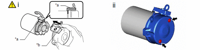
7. INSTALL STARTER YOKE ASSEMBLY

|
*1 | Starter Yoke Assembly |
*2 | Starter Drive Housing Assembly |
|
*a | Cutout |
*b | Protrusion |
(1) Align the cutout of the starter yoke assembly with the protrusion of the starter drive housing assembly.
(2) Using a T25 "TORX" socket wrench, install the 2 through bolts.
Torque:
6.0 N·m {61 kgf·cm, 53 in·lbf}
8. INSTALL PLUNGER

|
*a | Area to be Careful of Pinching |
*b | Protrusion of Plunger |
(1) Hang the hook of the plunger on the pinion drive lever and install the repair service starter kit.
NOTICE:
- Make sure the return spring is not resting on the protrusion of the plunger or pushed between the magnet switch and plunger.
- Install the plunger cover so that the ventilation hole is positioned as shown in the illustration.
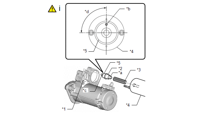
9. INSTALL SERVICE STARTER KIT
|
*1 | Pinion Drive Lever |
*2 | Plunger |
|
*3 | Return Spring |
*4 | Magnet Switch |
|
*5 | Plunger Cover |
- | - |
|
*a | Protrusion |
*b | Ventilation Hole |
|
*c | Hook |
*d | 90° |
(1) Install the 2 nuts.
Torque:
7.5 N·m {76 kgf·cm, 66 in·lbf}
10. INSTALL STARTER INRUSH CURRENT REDUCTION RELAY

|
*a | Lead Wire |
- | - |
Torque:
Bolt :
7.9 N·m {81 kgf·cm, 70 in·lbf}
Nut :
9.0 N·m {92 kgf·cm, 80 in·lbf}
11. INSTALL WIRE HARNESS

|
*1 | Wire Harness |
- | - |
|
*a | Nut |
*b | Noise Filter Harness |
Torque:
6.5 N·m {66 kgf·cm, 58 in·lbf}
12. INSTALL HARNESS


