Toyota Corolla Cross: Rear Power Window LH Auto Up / Down Function does not Operate with Rear Power Window Switch LH
DESCRIPTION
If the manual up and down functions operate normally but the auto up and down functions do not, the power window control system may be in fail-safe mode.
If power window initialization has not been performed, the auto up and down functions will not operate.
WIRING DIAGRAM
Click here .gif)
CAUTION / NOTICE / HINT
NOTICE:
- If the power window regulator motor assembly (for rear LH door) has been replaced with a new one, initialize the power window control system.
Click here
- Check that power window system customize settings "RL Window Auto Up Function" and "RL Window Auto Down Function" are set to "Enable" before performing the following procedure.
Click here
- After the catch protection function has operated, the auto up function will not operate the first time the power window auto up switch is operated. The auto up function will operate normally after the first power window switch operation.
- Before replacing the main body ECU (multiplex network body ECU), refer to Registration.*1
- for HEV Model:
Click here
- for Gasoline Model:
Click here
- *1: w/ Smart Key System
- for HEV Model:
HINT:
If the pulse sensor built into the power window regulator motor assembly (for rear LH door) is malfunctioning, the power window control system will enter fail-safe mode. The remote up and down and auto up and down functions cannot be operated during fail-safe mode. However, the power window can be closed by holding the rear power window regulator switch assembly (for rear LH door) at the auto up position, and opened manually by pushing down the rear power window regulator switch assembly (for rear LH door).
PROCEDURE
| 1. |
READ VALUE USING GTS |
(a) Read the Data List according to the display on the GTS.
Body Electrical > Main Body > Data List|
Tester Display | Measurement Item |
Range | Normal Condition |
Diagnostic Note |
|---|---|---|---|---|
|
RL Door Power Window AUTO Switch |
Rear LH door power window auto switch |
OFF or ON | OFF: Auto up or auto down switch not being operated ON: Auto up or auto down switch being operated |
- |
|
Tester Display |
|---|
| RL Door Power Window AUTO Switch |
OK:
On the GTS screen, ON or OFF is displayed accordingly.
| NG | .gif) | GO TO STEP 4 |
|
.gif)
| 2. |
PERFORM INITIALIZATION |
(a) Initialize the power window regulator motor assembly LH (for rear LH door).
Click here
|
| 3. |
CHECK POWER WINDOW CONTROL SYSTEM (AUTO UP / DOWN FUNCTION) |
(a) Check that the rear LH door power window moves when the auto up and down functions of the rear power window regulator switch assembly (for rear LH door) are operated.
Click here
OK:
Rear LH door auto up and down functions are normal.
| OK | | END (PROBLEM DUE TO INITIALIZATION FAILURE) |
| NG | | REPLACE POWER WINDOW REGULATOR MOTOR ASSEMBLY (for Rear LH Door) |
| 4. |
INSPECT REAR POWER WINDOW REGULATOR SWITCH ASSEMBLY (for Rear LH Door) |
Click here
| NG | | REPLACE REAR POWER WINDOW REGULATOR SWITCH ASSEMBLY (for Rear LH Door) |
|
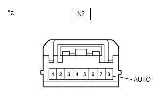
| 5. |
CHECK HARNESS AND CONNECTOR (REAR POWER WINDOW REGULATOR SWITCH ASSEMBLY - POWER WINDOW REGULATOR MOTOR ASSEMBLY (for Rear LH Door)) |
(a) Disconnect the N3 power window regulator motor assembly (for rear LH door) connector.
(b) Measure the resistance according to the value(s) in the table below.
Standard Resistance:
|
Tester Connection | Condition |
Specified Condition |
|---|---|---|
|
N2-8 (AUTO) - N3-4 (AUTO) |
Always | Below 1 Ω |
|
N2-8 (AUTO) or N3-4 (AUTO) - Body ground |
Always | 10 kΩ or higher |
| NG | | REPAIR OR REPLACE HARNESS OR CONNECTOR |
|
| 6. |
CHECK POWER WINDOW REGULATOR MOTOR ASSEMBLY (for Rear LH Door) |
(a) Connect the N3 power window regulator motor assembly (for rear LH door) connector.
| (b) Measure the voltage according to the value(s) in the table below. Standard Voltage:
|
|
| OK | | REPLACE MAIN BODY ECU (MULTIPLEX NETWORK BODY ECU) |
| NG | | REPLACE POWER WINDOW REGULATOR MOTOR ASSEMBLY (for Rear LH Door) |
READ NEXT:
 Rear Power Window RH Auto Up / Down Function does not Operate with Rear Power Window Switch RH
DESCRIPTION If the manual up and down functions operate normally but the auto up and down functions do not, the power window control system may be in fail-safe mode.
If power window initialization ha
All Power Windows do not Operate with Driver Side Door Key Cylinder or Wireless Transmitter
DESCRIPTION Wireless Transmitter-linked Function
When a key switch is pushed: 1) the door control receiver receives the wireless door lock signal; 2) the door control receiver sends a signal to the
Key-off Operation Function Operates even if Operating Conditions are not Satisfied
DESCRIPTION When the front doors are closed, each power window regulator motor assembly can be operated for approximately 45 seconds after the ignition switch is turned from ON to off by receiving ope
SEE MORE:
 Communication Error from ECM to VSC Invalid Serial Data Received (P163181)
DESCRIPTION The skid control ECU (brake booster with master cylinder assembly) sends signals such as brake request signals to the hybrid vehicle control ECU. When the hybrid vehicle control ECU detects logic error signals sent from the skid control ECU (brake booster with master cylinder assembly) f
Fuel Pump Ecu
RemovalREMOVAL CAUTION / NOTICE / HINT COMPONENTS (REMOVAL)
Procedure Part Name Code
1 DECK TRIM SIDE PANEL ASSEMBLY LH
64740C -
- -
2 FUEL PUMP CONTROL ECU
89571
- -
3 FUEL PUMP CONTROL ECU BRACKET
