Toyota Corolla Cross: Purge Valve
Removal
REMOVAL
CAUTION / NOTICE / HINT
COMPONENTS (REMOVAL)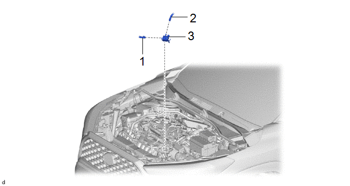
|
Procedure | Part Name Code |
.png) |
.png) |
 |
|---|---|---|---|---|---|
|
1 | NO. 2 FUEL VAPOR FEED HOSE |
23827A | - |
- | - |
|
2 | NO. 1 FUEL VAPOR FEED HOSE |
23826 | - |
- | - |
|
3 | PURGE VALVE (PURGE VSV) |
25860 | - |
- | - |
PROCEDURE
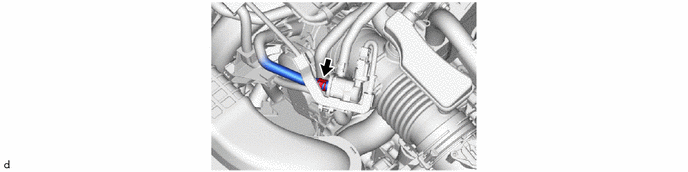
1. DISCONNECT NO. 2 FUEL VAPOR FEED HOSE
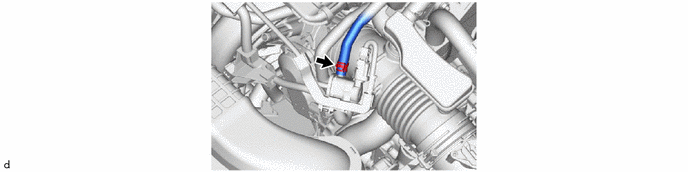
2. DISCONNECT NO. 1 FUEL VAPOR FEED HOSE
3. REMOVE PURGE VALVE (PURGE VSV)
Inspection
INSPECTION
PROCEDURE
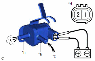
1. INSPECT PURGE VALVE (PURGE VSV)
(a) Measure the resistance according to the value(s) in the table below.
Standard Resistance:
|
Tester Connection | Condition |
Specified Condition |
|---|---|---|
|
1 - 2 | 20°C (68°F) |
23 to 26 Ω |
If the result is not as specified, replace the purge valve (purge VSV).
| (b) Apply battery voltage between the terminals of the purge valve (purge VSV) and check that the following occurs when blowing air into the port (E). OK:
If the result is not as specified, replace the purge valve (purge VSV). |
|
Installation
INSTALLATION
CAUTION / NOTICE / HINT
COMPONENTS (INSTALLATION)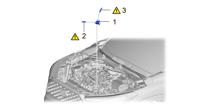
|
Procedure | Part Name Code |
.png) |
.png) |
 |
|---|---|---|---|---|---|
|
1 | PURGE VALVE (PURGE VSV) |
25860 | - |
- | - |
|
2 | NO. 2 FUEL VAPOR FEED HOSE |
23827A |
|
- | - |
|
3 | NO. 1 FUEL VAPOR FEED HOSE |
25826 |
|
- | - |
.gif)
PROCEDURE
1. INSTALL PURGE VALVE (PURGE VSV)
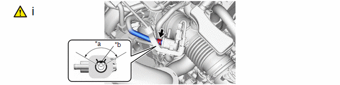
2. CONNECT NO. 2 FUEL VAPOR FEED HOSE
|
*a | 120° |
*b | Paint Mark |
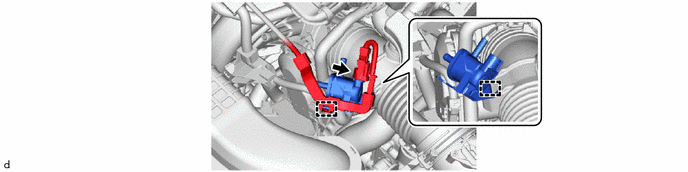
(1) Connect the No. 2 fuel vapor feed hose to the purge valve (purge VSV) and slide the clip to secure it.
HINT:
Engage the clip within the area shown in the illustration.
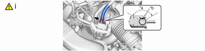
3. CONNECT NO. 1 FUEL VAPOR FEED HOSE
|
*a | 120° |
*b | Paint Mark |
(1) Connect the No. 1 fuel vapor feed hose to the purge valve (purge VSV) and slide the clip to secure it.
HINT:
Engage the clip within the area shown in the illustration.


