Toyota Corolla Cross: Pressure Control Solenoid "B" Circuit Short to Battery (P077512)
DESCRIPTION
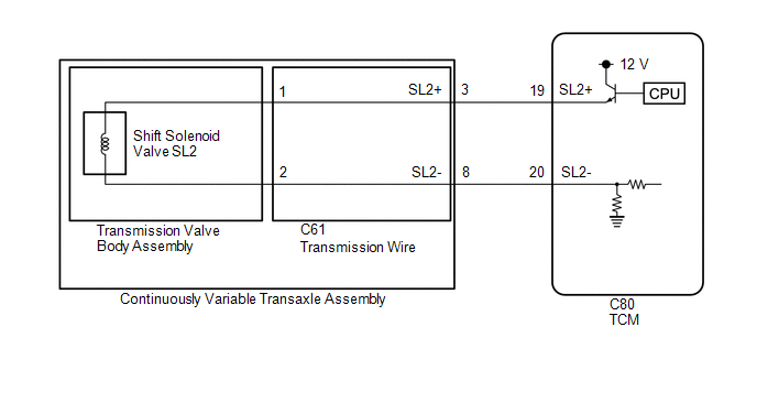
Using the current from the TCM, the shift solenoid valve SL2 controls the C2 clutch pressure in accordance with the requested shift mode.
|
DTC No. |
Detection Item |
DTC Detection Condition |
Trouble Area |
MIL |
Memory |
Note |
|---|---|---|---|---|---|---|
|
P077512 |
Pressure Control Solenoid "B" Circuit Short to Battery |
A short to +B is detected in the shift solenoid valve SL2 circuit for 1 second or more (1-trip detection logic). |
|
Comes on |
DTC stored |
SAE Code: P0967 |
MONITOR DESCRIPTION
This DTC indicates a short to +B in the shift solenoid valve SL2 circuit. If there is a short to +B in the shift solenoid valve SL2 circuit, the TCM detects the malfunction, illuminates the MIL and stores this DTC.
MONITOR STRATEGY
|
Related DTCs |
P0967: Pressure control solenoid "B" (Shift solenoid valve SL2)/Range check (High current) |
|
Required sensors/Components |
Shift solenoid valve SL2 |
|
Frequency of operation |
Continuous |
|
Duration |
1 sec. |
|
MIL operation |
Immediate |
|
Sequence of operation |
None |
TYPICAL ENABLING CONDITIONS
All|
The monitor will run whenever the following DTCs are not stored |
None |
|
Solenoid current cut status |
Not cut |
|
Ignition switch |
ON |
|
Starter |
OFF |
|
Battery voltage |
8 V or more and 11.499 V or less |
|
Target current (0.1 sec. or more) |
0.9 A or less |
|
Battery voltage |
11.5 V or more and 16 V or less |
|
Target current (0 sec. or more) |
1 A or less |
TYPICAL MALFUNCTION THRESHOLDS
Any of the following conditions are met: Condition (A) or (B)
Condition (A)|
Auxiliary battery voltage |
8 V or more and 11.499 V or less |
|
Solenoid current |
More than 1.145 A |
|
Auxiliary battery voltage |
11.5 V or more and 16 V or less |
|
Solenoid current |
More than 1.22 A |
COMPONENT OPERATING RANGE
Both of the following conditions are met: Condition (A) and (B)
Condition (A)|
Auxiliary battery voltage |
8 V or more and 11.499 V or less |
|
Solenoid current |
1.145 A or less |
|
Auxiliary battery voltage |
11.5 V or more and 16 V or less |
|
Solenoid current |
1.22 A or less |
CONFIRMATION DRIVING PATTERN
CAUTION:
When performing the confirmation driving pattern, obey all speed limits and traffic laws.
HINT:
- After repairs have been completed, clear the DTCs and then check that the vehicle has returned to normal by performing the following All Readiness check procedure.
- When clearing the permanent DTCs, refer to the Clear Permanent DTC procedure.
Click here
.gif)
- Clear the DTCs (even if no DTCs are stored, perform the clear DTC procedure).
- Turn the ignition switch off and wait for 2 minutes or more.
- Turn the ignition switch to ON and turn the GTS on.
- Start the engine.
- Perform the D Position Shift Test inspection in Road Test. [*1]
Click here
HINT:
[*1]: Normal judgment procedure.
The normal judgment procedure is used to complete DTC judgment and also used when clearing permanent DTCs.
- Stop the vehicle.
- Enter the following menus: Powertrain / Transmission / Utility / All Readiness.
- Input the DTC: P077512.
- Check the DTC judgment result.
GTS Display
Description
NORMAL
- DTC judgment completed
- System normal
ABNORMAL
- DTC judgment completed
- System abnormal
INCOMPLETE
- DTC judgment not completed
- Perform driving pattern after confirming DTC enabling conditions
N/A
- Unable to perform DTC judgment
- Number of DTCs which do not fulfill DTC preconditions has reached ECU memory limit
HINT:
- If the judgment result shows NORMAL, the system is normal.
- If the judgment result shows ABNORMAL, the system has a malfunction.
- If the judgment result shows INCOMPLETE or N/A, perform the normal judgment procedure again.
WIRING DIAGRAM
CAUTION / NOTICE / HINT
NOTICE:
- Perform the universal trip to clear permanent DTCs.
Click here
- Perform registration and/or initialization when parts related to the continuously
variable transaxle system are replaced.
Click here
- Check that no DTCs are stored after performing initialization.
Click here
PROCEDURE
|
1. |
INSPECT TRANSMISSION WIRE (SHIFT SOLENOID VALVE SL2) |
|
(a) Disconnect the transmission wire connector. |
|
(b) Measure the resistance according to the value(s) in the table below.
Standard Resistance:
|
Tester Connection |
Condition |
Specified Condition |
|---|---|---|
|
3 (SL2+) - Other terminals |
Always |
10 kΩ or higher |
|
8 (SL2-) - Other terminals |
Always |
10 kΩ or higher |
(c) Connect the transmission wire connector.
| NG | .gif) |
GO TO STEP 4 |
|
.gif)
|
2. |
CHECK HARNESS AND CONNECTOR (TRANSMISSION WIRE - TCM) |
(a) Disconnect the C80 TCM connector.
(b) Measure the resistance according to the value(s) in the table below.
Standard Resistance:
|
Tester Connection |
Condition |
Specified Condition |
|---|---|---|
|
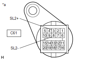
C80-19 (SL2+) - Other terminals |
Always |
10 kΩ or higher |
|
C80-20 (SL2-) - Other terminals |
Always |
10 kΩ or higher |
(c) Connect the C80 TCM connector.
| NG | |
REPAIR OR REPLACE HARNESS OR CONNECTOR (TRANSMISSION WIRE - TCM) |
|
|
3. |
REPLACE TCM |
Click here
| NEXT | |
PERFORM REGISTRATION AND INITIALIZATION for Registration: Click here for Initialization: Click here |
|
4. |
INSPECT TRANSMISSION WIRE |
(a) Disconnect the C61 transmission wire connector.
|
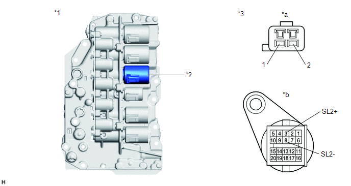
*1 |
Transmission Valve Body Assembly |
*2 |
Shift Solenoid Valve SL2 |
|
*3 |
Transmission Wire |
- |
- |
|
*a |
Shift Solenoid Valve Side |
*b |
Wire Harness Connector Side |
(b) Disconnect the transmission wire connector from the shift solenoid valve SL2.
Click here
(c) Measure the resistance according to the value(s) in the table below.
Standard Resistance:
|
Tester Connection |
Condition |
Specified Condition |
|---|---|---|
|
1 (shift solenoid valve side) or 3 (SL2+) (wire harness connector side) - All other terminals |
Always |
10 kΩ or higher |
|
2 (shift solenoid valve side) or 8 (SL2-) (wire harness connector side) - All other terminals |
Always |
10 kΩ or higher |
| NG | |
REPLACE TRANSMISSION WIRE |
|
|
5. |
REPLACE TRANSMISSION VALVE BODY ASSEMBLY |
Click here
| NEXT | |
PERFORM REGISTRATION AND INITIALIZATION for Registration: Click here for Initialization: Click here |


