Toyota Corolla Cross: Transmission Fluid Pressure Sensor/Switch "A" Circuit Short To Ground (P084011)
DESCRIPTION
The TCM performs learning control for the belt clamping pressure based on the belt clamping pressure signal, which is output by the oil pressure sensor.
|
DTC No. |
Detection Item |
DTC Detection Condition |
Trouble Area |
MIL |
Memory |
Note |
|---|---|---|---|---|---|---|
|
P084011 |
Transmission Fluid Pressure Sensor/Switch "A" Circuit Short To Ground |
When 2 seconds or more have elapsed since engine start, a short to ground is detected in the oil pressure sensor circuit for 0.5 seconds or more (1-trip detection logic). |
|
Comes on |
DTC stored |
SAE Code: P0842 |
MONITOR DESCRIPTION
This DTC indicates a short to ground in the oil pressure sensor circuit. If there is a short to ground in the oil pressure sensor circuit, the TCM detects the malfunction, illuminates the MIL and stores a DTC.
MONITOR STRATEGY
|
Related DTCs |
P0842: Oil pressure sensor/Range check (Low voltage) |
|
Required sensors/Components |
Oil pressure sensor |
|
Frequency of operation |
Continuous |
|
Duration |
0.5 sec. |
|
MIL operation |
Immediate |
|
Sequence of operation |
None |
TYPICAL ENABLING CONDITIONS
|
The monitor will run whenever the following DTCs are not stored |
None |
|
Starter |
OFF |
|
Auxiliary battery voltage |
8 V or more |
|
Ignition switch |
ON |
TYPICAL MALFUNCTION THRESHOLDS
|
Oil pressure sensor voltage |
Less than 0.28 V |
COMPONENT OPERATING RANGE
|
Oil pressure sensor voltage |
0.28 V or more and 4.9 V or less |
CONFIRMATION DRIVING PATTERN
HINT:
- After repairs have been completed, clear the DTCs and then check that the vehicle has returned to normal by performing the following All Readiness check procedure.
- When clearing the permanent DTCs, refer to the Clear Permanent DTC procedure.
Click here
.gif)
- Clear the DTCs (even if no DTCs are stored, perform the clear DTC procedure).
- Turn the ignition switch off and wait for 2 minutes or more.
- Turn the ignition switch to ON and turn the GTS on.
- Start the engine and wait for 5 seconds or more. [*1]
HINT:
[*1]: Normal judgment procedure.
The normal judgment procedure is used to complete DTC judgment and also used when clearing permanent DTCs.
- Enter the following menus: Powertrain / Transmission / Utility / All Readiness.
- Input the DTC: P084011.
- Check the DTC judgment result.
GTS Display
Description
NORMAL
- DTC judgment completed
- System normal
ABNORMAL
- DTC judgment completed
- System abnormal
INCOMPLETE
- DTC judgment not completed
- Perform driving pattern after confirming DTC enabling conditions
N/A
- Unable to perform DTC judgment
- Number of DTCs which do not fulfill DTC preconditions has reached ECU memory limit
HINT:
- If the judgment result shows NORMAL, the system is normal.
- If the judgment result shows ABNORMAL, the system has a malfunction.
- If the judgment result shows INCOMPLETE or N/A, perform the normal judgment procedure again.
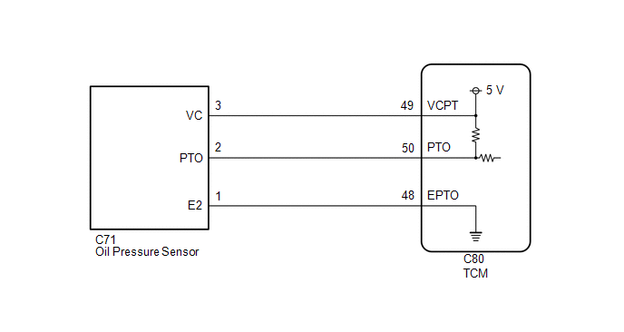
WIRING DIAGRAM
CAUTION / NOTICE / HINT
CAUTION:
- Do not perform a stall test if there are any people or objects near the
vehicle.
.png)
- The vehicle could begin moving suddenly, resulting in a serious accident.
- Do not perform a stall test if any wheel chock is out of position.
.png)
- The vehicle could begin moving suddenly, resulting in a serious accident.
- Do not perform the stall test on a slippery or low-friction surface that
could allow the tires to spin.
.png)
- The vehicle could begin moving suddenly, resulting in a serious accident.
NOTICE:
- Perform the universal trip to clear permanent DTCs.
Click here
- Perform registration and/or initialization when parts related to the continuously
variable transaxle system are replaced.
Click here
- Check that no DTCs are stored after performing initialization.
Click here
PROCEDURE
|
1. |
READ VALUE USING GTS (BELT CLAMPING FORCE SENSOR) |
CAUTION:
A stall speed test should always be performed with at least 2 people. One person should observe the condition of the wheels and wheel chocks while the other is performing the test.
NOTICE:
- This test must be performed after checking and confirming that the engine is normal.
- Perform this test with the CVT fluid temperature between 50 and 100°C (122 and 212°F).
- Perform this test with the air conditioning off.
- Do not perform the stall speed test for longer than 5 seconds.
- When performing the stall speed test repeatedly, wait for 15 seconds or more between tests.
- Perform this test with the AUTO function (shift-linked function) of the electric parking brake system off.
(a) Warm up the engine.
(b) Fully apply the parking brake and chock all 4 wheels.
HINT:
When the parking brake indicator (red) is illuminated after the electric parking brake switch (electric parking brake switch assembly) has been pulled to the lock side, the maximum amount of braking force is applied if the electric parking brake switch (electric parking brake switch assembly) is pulled to the lock side one more time.
(c) Enter the following menus:
(d) According to the display on the GTS, perform the Active Test.
Powertrain > Transmission > Active Test|
Tester Display |
Measurement Item |
Control Range |
Diagnostic Note |
|---|---|---|---|
|
Activate the TC Terminal |
Turn on and off TC and TE1 (CG) connection |
ON or OFF |
|
(e) Enter the following menus:
(f) According to the display on the GTS, read the Data List.
Powertrain > Transmission > Data List|
Tester Display |
Measurement Item |
Range |
Normal Condition |
Diagnostic Note |
|---|---|---|---|---|
|
Belt Clamping Force Sensor |
Secondary oil pressure value |
Min.: -64 MPa Max.: 63.998 MPa |
Secondary oil pressure inspection:
|
- |
|
Active Test Display |
|---|
|
Activate the TC Terminal |
|
Data List Display |
|---|
|
Belt Clamping Force Sensor |
|
Result |
Proceed to |
|---|---|
|
Data List value is normal |
A |
|
Data List value is not normal |
B |
| B | .gif) |
GO TO STEP 3 |
|
.gif)
|
2. |
REPLACE TCM |
Click here
| NEXT | |
PERFORM REGISTRATION AND INITIALIZATION for Registration: Click here for Initialization: Click here |
|
3. |
CHECK TCM (VCPT TERMINAL VOLTAGE) |
|
(a) Disconnect the oil pressure sensor connector. |
|
.png)
(b) Turn the ignition switch to ON.
(c) Measure the voltage according to the value(s) in the table below.
Standard Voltage:
|
Tester Connection |
Condition |
Specified Condition |
|---|---|---|
|
C71-3 (VC) - C71-1 (E2) |
Ignition switch ON |
4.75 to 5.25 V |
(d) Connect the oil pressure sensor connector.
| NG | |
GO TO STEP 10 |
|
|
4. |
CHECK HARNESS AND CONNECTOR (OIL PRESSURE SENSOR - TCM) |
(a) Disconnect the C71 oil pressure sensor connector.
(b) Disconnect the C80 TCM connector.
(c) Measure the resistance according to the value(s) in the table below.
Standard Resistance:
|
Tester Connection |
Condition |
Specified Condition |
|---|---|---|
|
C71-2 (PTO) - C80-50 (PTO) |
Always |
Below 1 Ω |
|
C71-2 (PTO) or C80-50 (PTO) - Body ground and other terminals |
Always |
10 kΩ or higher |
(d) Connect the C80 TCM connector.
(e) Connect the C71 oil pressure sensor connector.
| NG | |
REPAIR OR REPLACE HARNESS OR CONNECTOR (OIL PRESSURE SENSOR - TCM) |
|
|
5. |
REPLACE OIL PRESSURE SENSOR |
Click here
|
|
6. |
CLEAR DTC |
(a) Clear the DTCs.
Powertrain > Transmission > Clear DTCs
|
|
7. |
PERFORM INITIALIZATION |
Click here
|
|
8. |
CONFIRM WHETHER MALFUNCTION HAS BEEN SUCCESSFULLY REPAIRED (P084011) |
(a) Start the engine and wait for 5 seconds or more.
(b) Enter the following menus:
(c) Read the DTCs.
Powertrain > Transmission > Trouble Codes|
Result |
Proceed to |
|---|---|
|
DTCs are not output |
A |
|
DTC P084011 is output |
B |
| A | |
END |
|
|
9. |
REPLACE TCM |
Click here
| NEXT | |
PERFORM REGISTRATION AND INITIALIZATION for Registration: Click here for Initialization: Click here |
|
10. |
CHECK HARNESS AND CONNECTOR (OIL PRESSURE SENSOR - TCM) |
(a) Disconnect the C71 oil pressure sensor connector.
(b) Disconnect the C80 TCM connector.
(c) Measure the resistance according to the value(s) in the table below.
Standard Resistance:
|
Tester Connection |
Condition |
Specified Condition |
|---|---|---|
|
C71-3 (VC) - C80-49 (VCPT) |
Always |
Below 1 Ω |
|
C71-1 (E2) - C80-48 (EPTO) |
Always |
Below 1 Ω |
|
C71-3 (VC) or C80-49 (VCPT) - Body ground and other terminals |
Always |
10 kΩ or higher |
|
C71-1 (E2) or C80-48 (EPTO) - Body ground and other terminals |
Always |
10 kΩ or higher |
(d) Connect the C80 TCM connector.
(e) Connect the C71 oil pressure sensor connector.
| NG | |
REPAIR OR REPLACE HARNESS OR CONNECTOR (OIL PRESSURE SENSOR - TCM) |
|
|
11. |
REPLACE TCM |
Click here
| NEXT | |
PERFORM REGISTRATION AND INITIALIZATION for Registration: Click here for Initialization: Click here |
READ NEXT:
 Transmission Fluid Pressure Sensor/Switch "A" Circuit Short To Battery or Open
(P084015)
Transmission Fluid Pressure Sensor/Switch "A" Circuit Short To Battery or Open
(P084015)
DESCRIPTION
Refer to DTC P084011.
Click here
DTC No.
Detection Item
DTC Detection Condition
Trouble Area
MIL
Memory
No
Pressure Control Solenoid "M" Circuit Short to Battery (P08C312)
DESCRIPTION
Using the current from the TCM, the shift solenoid valve SLG controls the B1
brake when the shift lever is in R, and S1 synchronizer when the shift lever is
in P, N, D or M.
Pressure Control Solenoid "M" Circuit Short to Ground or Open (P08C314)
DESCRIPTION
Refer to DTC P08C312.
Click here
DTC No.
Detection Item
DTC Detection Condition
Trouble Area
MIL
Memory
No
SEE MORE:
 Second Row Left Seat Belt Pretensioner Deployment Control Circuit Open (B007313)
DESCRIPTION
DTC No. Detection Item
DTC Detection Condition Trouble Area
Warning Indicate Test Mode / Check Mode
B007313 Second Row Left Seat Belt Pretensioner Deployment Control Circuit Open
The airbag ECU assembly detects an open in the rear pretensioner s
Telephone And Gps Antenna
Removal
REMOVAL
CAUTION / NOTICE / HINT
COMPONENTS (REMOVAL)
Procedure
Part Name Code
1
ROOF HEADLINING ASSEMBLY
63310
-
-
-
Procedure
Par
