Toyota Corolla Cross: Power Steering Torque Sensor "B" Supply Voltage Circuit Voltage Above Threshold (C151B17)
DESCRIPTION
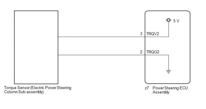
The power steering ECU assembly supplies a voltage of 5 V to the torque sensor (electric power steering column sub-assembly) and monitors the voltage value of the Hall IC inside the torque sensor (electric power steering column sub-assembly) which changes in response to changes in the magnetic flux density (steering torque) detected by the Hall IC, and calculates the assist torque.
While DTC C151B17 is detected, power assist is stopped or assist amount is limited due to fail-safe operation.
|
DTC No. |
Detection Item |
DTC Detection Condition |
Trouble Area |
Warning Indicate |
|---|---|---|---|---|
|
C151B17 |
Power Steering Torque Sensor "B" Supply Voltage Circuit Voltage Above Threshold |
TRQV2 voltage is high voltage abnormality |
|
EPS warning light: Comes on |
WIRING DIAGRAM
CAUTION / NOTICE / HINT
NOTICE:
- When the electric power steering column sub-assembly has been replaced,
perform Power Steering ECU Initial Setting (assist map writing).
Click here
.gif)
- When the power steering ECU assembly has been replaced, perform Power Steering
ECU Initial Setting (assist map writing).
Click here
PROCEDURE
|
1. |
INSPECT TORQUE SENSOR (ELECTRIC POWER STEERING COLUMN SUB-ASSEMBLY) (CHECK FOR SHORT) |
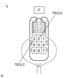
(a) Disconnect the z7 power steering ECU assembly connector.
(b) Measure the resistance according to the value(s) in the table below.
Standard Resistance:
|
Tester Connection |
Condition |
Specified Condition |
|---|---|---|
|
z7-3 (TRQV2) - Body ground |
Always |
10 kΩ or higher |
|
z7-3 (TRQV2) - z7-2 (TRQG2) |
Always |
10 kΩ or higher |
| NG | .gif) |
REPLACE ELECTRIC POWER STEERING COLUMN SUB-ASSEMBLY |
|
.gif)
|
2. |
CONFIRM MODEL |
(a) Choose the model to be inspected.
|
Result |
Proceed to |
|---|---|
|
for HEV Model |
A |
|
for Gasoline Model |
B |
| B | |
GO TO STEP 4 |
|
|
3. |
INSPECT POWER STEERING ECU ASSEMBLY (POWER SOURCE OF TORQUE SENSOR) |
(a) Start the engine.
|
(b) Measure the voltage according to the value(s) in the table below. Standard Voltage:
|
|
| OK | |
REPLACE ELECTRIC POWER STEERING COLUMN SUB-ASSEMBLY |
| NG | |
REPLACE POWER STEERING ECU ASSEMBLY |
|
4. |
INSPECT POWER STEERING ECU ASSEMBLY (POWER SOURCE OF TORQUE SENSOR) |
(a) Start the engine.
|
(b) Measure the voltage according to the value(s) in the table below. Standard Voltage:
|
|
| OK | |
REPLACE ELECTRIC POWER STEERING COLUMN SUB-ASSEMBLY |
| NG | |
REPLACE POWER STEERING ECU ASSEMBLY |
READ NEXT:
 Power Steering Motor "A" Supply Voltage Circuit Voltage Below Threshold (C155A16,C155A17,C155B16,C155B17)
DESCRIPTION
If a problem occurs in the system, the power source relay circuit and the motor
relay circuit are shut off to stop power assist. The ECU must be replaced when there
is a problem with
Heavy Steering Feel (EPS Warning Light (Yellow))
PROCEDURE
1.
CONFIRM MODEL
(a) Choose the model to be inspected.
Result
Proceed to
for HEV Model
A
EPS Warning Light Circuit
DESCRIPTION
Use the following procedure if no DTCs are output but the EPS warning light is
illuminated continuously.
The power steering ECU assembly controls the warning light in the combination
SEE MORE:
 Power Back Door does not Operate Using Outside Switch
DESCRIPTION The No. 1 power back door control switch signal is sent to the multiplex network door ECU.
If the power back door does not operate using the No. 1 power back door control switch, a No. 1 power back door control switch circuit malfunction is a possible cause. WIRING DIAGRAM
CAUTION / N
Installation
INSTALLATION CAUTION / NOTICE / HINT COMPONENTS (INSTALLATION)
Procedure Part Name Code
1 NO. 2 INSTRUMENT PANEL WIRE
82142
- -
2 INSTRUMENT PANEL PASSENGER AIRBAG ASSEMBLY
73960A -
- -
3 INSTRUMENT PAN
