Toyota Corolla Cross: Power Steering Motor "A" Supply Voltage Circuit Voltage Below Threshold (C155A16,C155A17,C155B16,C155B17)
DESCRIPTION
If a problem occurs in the system, the power source relay circuit and the motor relay circuit are shut off to stop power assist. The ECU must be replaced when there is a problem with the relays because the relays are built into the ECU.
|
DTC No. |
Detection Item |
DTC Detection Condition |
Trouble Area |
Warning Indicate |
|---|---|---|---|---|
|
C155A16 |
Power Steering Motor "A" Supply Voltage Circuit Voltage Below Threshold |
Motor "A" PIG voltage is 3.5 V or less |
|
EPS warning light: Comes on |
|
C155A17 |
Power Steering Motor "A" Supply Voltage Circuit Voltage Above Threshold |
Motor "1" PIG voltage is 19.6 V or more |
|
EPS warning light: Comes on |
|
C155B16 |
Power Steering Motor "B" Supply Voltage Circuit Voltage Below Threshold |
Motor "B" PIG voltage is 3.5 V or less |
|
EPS warning light: Comes on |
|
C155B17 |
Power Steering Motor "B" Supply Voltage Circuit Voltage Above Threshold |
Motor "2" PIG voltage is 19.6 V or more |
|
EPS warning light: Comes on |
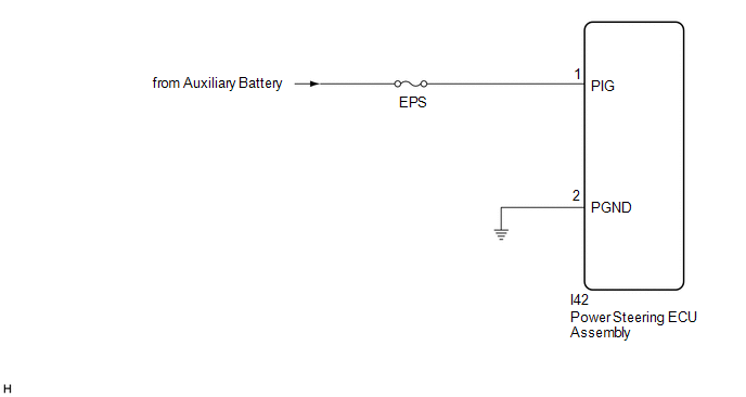
WIRING DIAGRAM
CAUTION / NOTICE / HINT
NOTICE:
- When the power steering ECU assembly has been replaced, perform Power Steering
ECU Initial Setting (assist map writing).
Click here
.gif)
- Inspect the fuses for circuits related to this system before performing the following procedure.
PROCEDURE
|
1. |
CHECK HARNESS AND CONNECTOR (POWER STEERING ECU ASSEMBLY - BODY GROUND) |
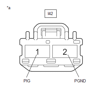
(a) Disconnect the I42 power steering ECU assembly connectors.
|
(b) Measure the voltage according to the value(s) in the table below. Standard Voltage:
|
|
(c) Measure the resistance according to the value(s) in the table below.
Standard Resistance:
|
Tester Connection |
Condition |
Specified Condition |
|---|---|---|
|
I42-2 (PGND) - Body ground |
Always |
Below 1 Ω |
| OK | .gif) |
REPLACE POWER STEERING ECU ASSEMBLY |
| NG | |
REPAIR OR REPLACE HARNESS OR CONNECTOR |
READ NEXT:
 Heavy Steering Feel (EPS Warning Light (Yellow))
PROCEDURE
1.
CONFIRM MODEL
(a) Choose the model to be inspected.
Result
Proceed to
for HEV Model
A
EPS Warning Light Circuit
DESCRIPTION
Use the following procedure if no DTCs are output but the EPS warning light is
illuminated continuously.
The power steering ECU assembly controls the warning light in the combination
Abnormal Feel at Steering End Position
SYSTEM DESCRIPTION
This vehicle employs end position contact shock reduction control for column
EPS, designed to protect components by suppressing torque input when steering mechanism
components
SEE MORE:
 Precaution
PRECAUTION
PRECAUTION FOR DISCONNECTING CABLE FROM NEGATIVE AUXILIARY BATTERY
TERMINAL
NOTICE:
After the ignition switch is turned off, there may be a waiting
time before disconnecting the negative (-) auxiliary battery terminal.
Click here
HINT:
When disconnecting and reconnecting the a
Clearance Warning ECU Communication Stop Mode
DESCRIPTION
Detection Item
Symptom
Trouble Area
Clearance Warning ECU Communication Stop Mode
Communication stop for "Clearance Warning (Intuitive Parking Assist)"
is indicated on the "Communication Bus Check" scre
