Toyota Corolla Cross: Power Back Door cannot be Operated Using Any Switch
DESCRIPTION
The power back door controls the multiplex network door ECU and operates the power back door unit assembly and back door lock assembly.
If the power back door does not operate using any of the operations, a malfunction related to the power back door operation conditions or multiplex network door ECU are possible causes.
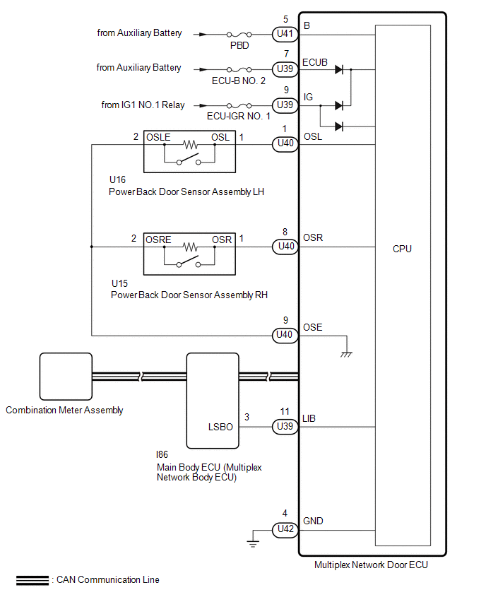
WIRING DIAGRAM
CAUTION / NOTICE / HINT
NOTICE:
- First perform the communication function inspections in How to Proceed with Troubleshooting to confirm that there are no CAN communication malfunctions before troubleshooting this problem.
Click here
.gif)
- Inspect fuses for circuits related to this system before performing the following procedure.
- This check is possible only when the "System Settings" customization setting using the multi-information display in the combination meter assembly is set to "On" (The default setting is "On").
Click here
- If the replacement, removal and installation of the multiplex network door ECU or disconnection of the connectors of the multiplex network door ECU has been performed, initialize the power back door system.
Click here
- If the 2-step unlock function is enabled via customize settings, only the driver door unlocks when the first unlock operation is performed and the power back door does not operate as all the doors are not unlocked.
PROCEDURE
|
1. | CHECK CUSTOMIZE SETTING (UNLOCK KEY TWICE FUNCTION) |
(a) Read the customize setting "Unlock Key Twice Function" according to the display on the GTS.
Click here
|
Result | Proceed to |
|---|---|
|
The customize setting is "Disable" |
A |
| The customize setting is "Enable" |
B |
| B |
.gif) | PERFORM CUSTOMIZE SETTING |
|
.gif)
| 2. |
CHECK CUSTOMIZE SETTING (WIRELESS UNLOCK TWICE FUNCTION) |
(a) Read the customize setting "Wireless Unlock Twice Function" according to the display on the GTS.
Click here
|
Result | Proceed to |
|---|---|
|
The customize setting is "Disable" |
A |
| The customize setting is "Enable" |
B |
| B |
| PERFORM CUSTOMIZE SETTING |
|
| 3. |
CHECK CUSTOMIZE SETTING (ENTRY UNLOCK TWICE FUNCTION) |
(a) Read the customize setting "Entry Unlock Twice Function" according to the display on the GTS.
for HEV Model: Click here
for Gasoline Model: Click here
|
Result | Proceed to |
|---|---|
|
The customize setting is "Disable" |
A |
| The customize setting is "Enable" |
B |
| B |
| PERFORM CUSTOMIZE SETTING for HEV Model: Click here for Gasoline Model: Click here
|
|
| 4. |
CHECK VEHICLE CONDITION |
(a) Check that the power back door function on the multi-information display in the combination meter assembly is set to ON.
Click here
|
Result | Proceed to |
|---|---|
|
Power back door function on the multi-information display in the combination meter assembly is set to ON (power back door system operation is permitted) |
A |
| Power back door function on the multi-information display in the combination meter assembly is set to OFF (power back door system operation is prohibited) |
B |
| B |
| SET POWER BACK DOOR FUNCTION TO ON (PERMIT POWER BACK DOOR SYSTEM OPERATION) |
|
| 5. |
CHECK POWER BACK DOOR SYSTEM CONDITION |
(a) Check the power back door system condition.
|
Result | Proceed to |
|---|---|
|
The malfunction symptom reproduces |
A |
| The malfunction symptom does not reproduce |
B |
| B |
| GO TO POWER BACK DOOR CANNOT BE OPERATED FREQUENTLY |
|
| 6. |
CLEAR DTC |
(a) Clear the DTCs.
Body Electrical > Back Door > Clear DTCs
|
| 7. |
CHECK FOR DTC |
(a) Check for DTCs.
Body Electrical > Back Door > Trouble Codes|
Result | Proceed to |
|---|---|
|
DTC is output | A |
|
DTC is not output | B |
| A |
| GO TO DIAGNOSTIC TROUBLE CODE CHART |
|
| 8. |
CHECK HARNESS AND CONNECTOR (MULTIPLEX NETWORK DOOR ECU - BATTERY AND BODY GROUND) |
(a) Disconnect the multiplex network door ECU connectors.
|
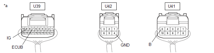
*a | Rear view of wire harness connector (to Multiplex Network Door ECU) |
- | - |
(b) Measure the resistance according to the value(s) in the table below.
Standard Resistance:
|
Tester Connection | Condition |
Specified Condition |
|---|---|---|
|
U42-4 (GND) - Body ground |
Always | Below 1 Ω |
(c) Measure the voltage according to the value(s) in the table below.
Standard Voltage:
|
Tester Connection | Switch Condition |
Specified Condition |
|---|---|---|
|
U39-7 (ECUB) - Body ground |
Ignition switch off | 11 to 14 V |
|
U41-5 (B) - Body ground |
Ignition switch off | 11 to 14 V |
|
U39-9 (IG) - Body ground |
Ignition switch ON | 11 to 14 V |
|
Ignition switch off | Below 1 V |
| NG | | REPAIR OR REPLACE HARNESS OR CONNECTOR |
|
| 9. |
READ VALUE USING GTS |
(a) Read the Data List according to the display on the GTS.
Body Electrical > Back Door > Data List|
Tester Display | Measurement Item |
Range | Diagnostic Note |
|---|---|---|---|
|
PBD Main Switch | Power back door ON/OFF signal |
ON or OFF | ON: Power back door ON OFF: Power back door off |
|
Door Lock Signal | Back door condition signal |
Lock or Unlock | Lock: Back door locked Unlock: Back door unlocked |
|
Tester Display |
|---|
| PBD Main Switch |
|
Door Lock Signal |
|
Result | Proceed to |
|---|---|
|
Either item is normal |
A |
| "PBD Main SW" item does not switch to "ON" or "OFF" according to main switch operation |
B |
| "Door Lock Signal" item does not switch to "Lock" or "Unlock" according to operation to lock or unlock all doors |
C |
| B |
| GO TO METER / GAUGE SYSTEM |
| C |
| GO TO STEP 13 |
|
| 10. |
READ VALUE USING GTS |
(a) Read the Data List according to the display on the GTS.
Body Electrical > Back Door > Data List|
Tester Display | Measurement Item |
Range | Normal Condition |
Diagnostic Note |
|---|---|---|---|---|
|
PBD Touch Sensor RH | Power back door sensor assembly RH signal |
ON, OFF or Open | ON: Power back door sensor assembly RH pressed OFF: Power back door sensor assembly RH not pressed Open: Power back door sensor assembly RH circuit open |
- |
| PBD Touch Sensor LH |
Power back door sensor assembly LH signal |
ON, OFF or Open | ON: Power back door sensor assembly LH pressed OFF: Power back door sensor assembly LH not pressed Open: Power back door sensor assembly LH circuit open |
- |
|
Tester Display |
|---|
| PBD Touch Sensor RH |
|
PBD Touch Sensor LH |
|
Result | Proceed to |
|---|---|
|
On the GTS screen, ON or OFF is displayed accordingly |
A |
| On the GTS screen, ON or OFF is not displayed accordingly or Open is displayed for power back door sensor assembly RH |
B |
| On the GTS screen, ON or OFF is not displayed accordingly or Open is displayed for power back door sensor assembly LH |
C |
| A |
| REPLACE MULTIPLEX NETWORK DOOR ECU |
| C |
| GO TO STEP 15 |
|
| 11. |
INSPECT POWER BACK DOOR SENSOR ASSEMBLY RH |
Click here
| NG | | REPLACE POWER BACK DOOR SENSOR ASSEMBLY RH |
|
| 12. |
CHECK HARNESS AND CONNECTOR (POWER BACK DOOR SENSOR ASSEMBLY RH - MULTIPLEX NETWORK DOOR ECU) |
(a) Disconnect the U15 power back door sensor assembly RH connector.
(b) Disconnect the U40 multiplex network door ECU connector.
(c) Measure the resistance according to the value(s) in the table below.
Standard Resistance:
|
Tester Connection | Condition |
Specified Condition |
|---|---|---|
|
U15-1 (OSR) - U40-8 (OSR) |
Always | Below 1 Ω |
|
U15-2 (OSRE) - U40-9 (OSE) |
Always | Below 1 Ω |
|
U15-1 (OSR) or U40-8 (OSR) - Body ground |
Always | 10 kΩ or higher |
|
U15-2 (OSRE) or U40-9 (OSE) - Body ground |
Always | 10 kΩ or higher |
| OK | | REPLACE MULTIPLEX NETWORK DOOR ECU |
| NG | | REPAIR OR REPLACE HARNESS OR CONNECTOR |
| 13. |
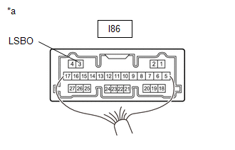
CHECK HARNESS AND CONNECTOR (MAIN BODY ECU [MULTIPLEX NETWORK BODY ECU] - MULTIPLEX NETWORK DOOR ECU) |
(a) Disconnect the I86 main body ECU (multiplex network body ECU) connector.
(b) Disconnect the U39 multiplex network door ECU connector.
(c) Measure the resistance according to the value(s) in the table below.
Standard Resistance:
|
Tester Connection | Condition |
Specified Condition |
|---|---|---|
|
U39-11 (LIB) - I86-3 (LSBO) |
Always | Below 1 Ω |
|
U39-11 (LIB) or I86-3 (LSBO) - Body ground |
Always | 10 kΩ or higher |
| NG | | REPAIR OR REPLACE HARNESS OR CONNECTOR |
|
| 14. |
CHECK MAIN BODY ECU (MULTIPLEX NETWORK BODY ECU) |
| (a) Remove the main body ECU (multiplex network body ECU) with the connector(s) still connected. Click here |
|
(b) Measure the voltage according to the value(s) in the table below.
Standard Voltage:
|
Tester Connection | Condition |
Specified Condition |
|---|---|---|
|
I86-3 (LSBO) - Body ground |
Always | 11 to 14 V |
| OK | | REPLACE MULTIPLEX NETWORK DOOR ECU |
| NG | | REPLACE MAIN BODY ECU (MULTIPLEX NETWORK BODY ECU) |
| 15. |
INSPECT POWER BACK DOOR SENSOR ASSEMBLY LH |
Click here
| NG | | REPLACE POWER BACK DOOR SENSOR ASSEMBLY LH |
|
| 16. |
CHECK HARNESS AND CONNECTOR (POWER BACK DOOR SENSOR ASSEMBLY LH - MULTIPLEX NETWORK DOOR ECU) |
(a) Disconnect the U16 power back door sensor assembly LH connector.
(b) Disconnect the U40 multiplex network door ECU connector.
(c) Measure the resistance according to the value(s) in the table below.
Standard Resistance:
|
Tester Connection | Condition |
Specified Condition |
|---|---|---|
|
U16-1 (OSL) - U40-1 (OSL) |
Always | Below 1 Ω |
|
U16-2 (OSLE) - U40-9 (OSE) |
Always | Below 1 Ω |
|
U16-1 (OSL) or U40-1 (OSL) - Body ground |
Always | 10 kΩ or higher |
|
U16-2 (OSLE) or U40-9 (OSE) - Body ground |
Always | 10 kΩ or higher |
| OK | | REPLACE MULTIPLEX NETWORK DOOR ECU |
| NG | | REPAIR OR REPLACE HARNESS OR CONNECTOR |


