Toyota Corolla Cross: Power Back Door does not Operate Using Cabin Switch
DESCRIPTION
The power back door control switch signal is sent to the multiplex network door ECU.
If the power back door does not operate using the power back door control switch, a power back door control switch circuit malfunction is a possible cause.
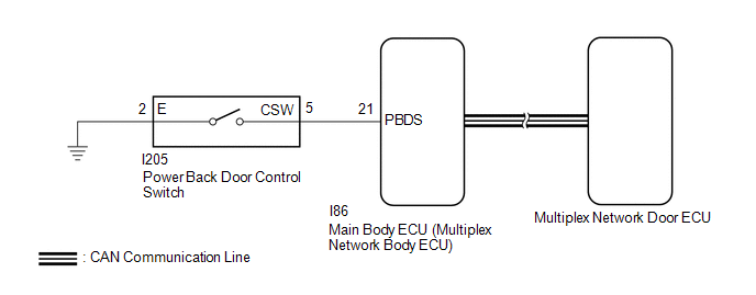
WIRING DIAGRAM
CAUTION / NOTICE / HINT
NOTICE:
- First perform the communication function inspections in How to Proceed with Troubleshooting to confirm that there are no CAN communication malfunctions before troubleshooting this problem.
Click here
.gif)
- If the replacement, removal and installation of the multiplex network door ECU or disconnection of the connectors of the multiplex network door ECU has been performed, initialize the power back door system.
Click here
- If the main body ECU (multiplex network body ECU) is replaced, refer to Registration.
for HEV Model: Click here
for Gasoline Model: Click here
PROCEDURE
|
1. | CHECK VEHICLE CONDITION |
(a) Check that the power back door function on the multi-information display in the combination meter assembly is set to ON.
Click here
|
Result | Proceed to |
|---|---|
|
Power back door function on the multi-information display in the combination meter assembly is set to ON (power back door system operation is permitted) |
A |
| Power back door function on the multi-information display in the combination meter assembly is set to OFF (power back door system operation is prohibited) |
B |
| B |
.gif) | SET POWER BACK DOOR FUNCTION TO ON (PERMIT POWER BACK DOOR SYSTEM OPERATION) |
|
.gif)
| 2. |
CHECK POWER BACK DOOR SYSTEM CONDITION |
(a) Check the power back door system condition.
|
Result | Proceed to |
|---|---|
|
The malfunction symptom reproduces |
A |
| The malfunction symptom does not reproduce |
B |
| B |
| GO TO POWER BACK DOOR CANNOT BE OPERATED FREQUENTLY |
|
| 3. |
READ VALUE USING GTS |
(a) Read the Data List according to the display on the GTS.
Body Electrical > Main Body > Data List|
Tester Display | Measurement Item |
Range | Normal Condition |
Diagnostic Note |
|---|---|---|---|---|
|
Back Door Operation Switch (Instrument) |
Power back door switch assembly signal |
OFF or ON | OFF: Power back door control switch off ON: Power back door control switch on |
- |
|
Tester Display |
|---|
| Back Door Operation Switch (Instrument) |
OK:
The power back door control switch functions as specified in the normal condition column.
| OK | | REPLACE MULTIPLEX NETWORK DOOR ECU |
|
| 4. |
INSPECT POWER BACK DOOR CONTROL SWITCH |
Click here
| NG | | REPLACE POWER BACK DOOR CONTROL SWITCH |
|
| 5. |
CHECK HARNESS AND CONNECTOR (POWER BACK DOOR CONTROL SWITCH - MAIN BODY ECU [MULTIPLEX NETWORK BODY ECU] AND BODY GROUND) |
(a) Disconnect the I205 power back door control switch connector.
(b) Disconnect the I86 main body ECU (multiplex network body ECU) connector.
(c) Measure the resistance according to the value(s) in the table below.
Standard Resistance:
|
Tester Connection | Condition |
Specified Condition |
|---|---|---|
|
I205-5 (CSW) - I86-21 (PBDS) |
Always | Below 1 Ω |
|
I205-2 (E) - Body ground |
Always | Below 1 Ω |
|
I205-5 (CSW) or I86-21 (PBDS) - Body ground |
Always | 10 kΩ or higher |
| OK | | REPLACE MAIN BODY ECU (MULTIPLEX NETWORK BODY ECU) |
| NG | | REPAIR OR REPLACE HARNESS OR CONNECTOR |


