Toyota Corolla Cross: Personal Light
Removal
REMOVAL
CAUTION / NOTICE / HINT
COMPONENTS (REMOVAL)
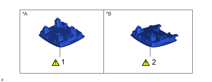
Procedure | Part Name Code |
|
|
|
1 | MAP LIGHT ASSEMBLY |
81260A |
|
- | - |
2 | MAP LIGHT ASSEMBLY |
81260A |
|
- | - |
*A | w/o Sliding Roof |
*B | w/ Sliding Roof |
PROCEDURE
1. REMOVE MAP LIGHT ASSEMBLY (w/o Sliding Roof)
(1) Using a moulding remover D, disengage the clips to remove the map light assembly.
(2) Disconnect the connector.
2. REMOVE MAP LIGHT ASSEMBLY (w/ Sliding Roof)
(1) Using a moulding remover D, disengage the clips and guides to remove the map light assembly.
(2) Disconnect the connector.
Inspection
INSPECTION
PROCEDURE
1. INSPECT MAP LIGHT ASSEMBLY
(a) Check the resistance.
(1) Measure the resistance according to the value(s) in the table below.
Standard Resistance:
Tester Connection | Condition |
Specified Condition |
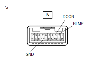
T6-2 (RLMP) - T6-3 (DOOR) |
Door linked switch on |
Below 1 Ω |
T6-2 (RLMP) - T6-17 (GND) |
Dome light switch on |
Below 1 Ω | If the result is not as specified, replace the map light assembly. |
|
*a | Component without harness connected
(Map Light Assembly) | | |
(b) Check the illumination.
(1) Apply auxiliary battery voltage to the map light assembly and check that the lights illuminate.
OK:
Tester Connection | Condition |
Specified Condition |
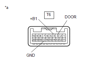
T6-4 (+B1) - Auxiliary battery positive (+) T6-17 (GND) - Auxiliary battery negative (-) |
Map light switch LH on |
Map light LH illuminates |
T6-4 (+B1) - Auxiliary battery positive (+) T6-17 (GND) - Auxiliary battery negative (-) |
Map light switch RH on |
Map light RH illuminates |
T6-4 (+B1) - Auxiliary battery positive (+) T6-17 (GND) - Auxiliary battery negative (-) |
Map light switches off and dome light switch on |
Map light LH and RH illuminate |
T6-4 (+B1) - Auxiliary battery positive (+) T6-3 (DOOR) - Auxiliary battery negative (-) |
Map light switches off and door linked switch on |
Map light LH and RH illuminate |
If the result is not as specified, replace the bulb or map light assembly. |
|
*a | Component without harness connected
(Map Light Assembly) | | |
Installation
INSTALLATION
CAUTION / NOTICE / HINT
COMPONENTS (INSTALLATION)
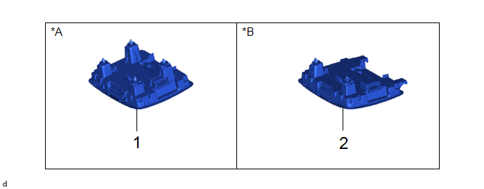
Procedure | Part Name Code |
|
|
|
1 | MAP LIGHT ASSEMBLY |
81260A | - |
- | - |
2 | MAP LIGHT ASSEMBLY |
81260A | - |
- | - |
*A | w/o Sliding Roof |
*B | w/ Sliding Roof |
PROCEDURE
1. INSTALL MAP LIGHT ASSEMBLY (w/o Sliding Roof)
2. INSTALL MAP LIGHT ASSEMBLY (w/ Sliding Roof)
READ NEXT:
REMOVAL CAUTION / NOTICE / HINT COMPONENTS (REMOVAL)
Procedure Part Name Code
1 REAR SEAT ASSEMBLY
- -
- -
2 REAR DOOR SCUFF PLATE
INSPECTION PROCEDURE 1. INSPECT REAR DOOR COURTESY LIGHT SWITCH ASSEMBLY LH
(a) Check the resistance.
(1) Measure the resistance according to the value(s) in the table below.
Standard Resis
SEE MORE:
DTC SUMMARY MALFUNCTION DESCRIPTION These DTCs indicate that the boost converter temperature sensor (lower) value is abnormal. The cause of this malfunction may be one of the following: Internal inverter malfunction
Inverter with converter assembly internal circuit malfunction
Hybrid cool
If a rear radar sensor detects a vehicle approaching from the right or
left at the rear of the vehicle and the system determines that the possibility
of a collision is high, this function will perform brake control to
reduce the likelihood of an impact with the approaching vehicle.
This function wi