Toyota Corolla Cross Owners & Service Manuals

Toyota Corolla Cross: Parts Location

PARTS LOCATION

ILLUSTRATION
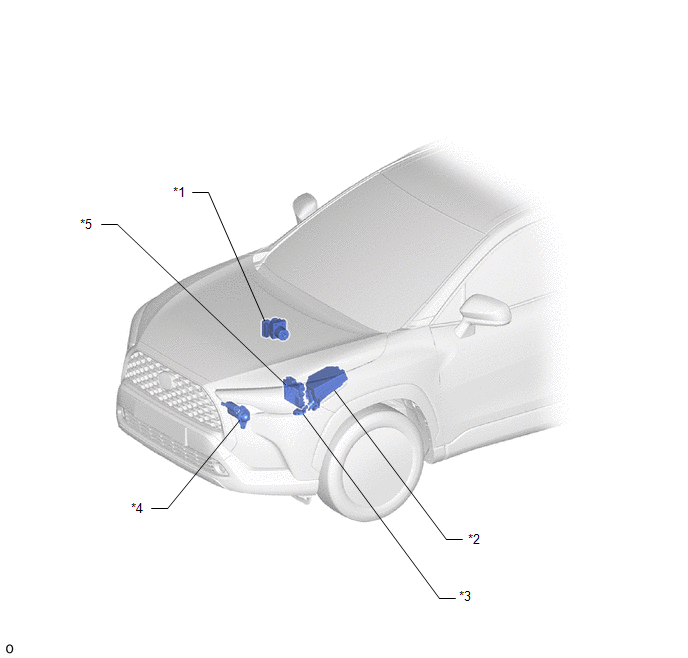
*1

SKID CONTROL ECU (BRAKE ACTUATOR ASSEMBLY)

*2

NO. 1 ENGINE ROOM RELAY BLOCK

- IGP-MAIN RELAY

*3

PARK/NEUTRAL POSITION SWITCH

*4

STARTER ASSEMBLY

*5

ECM

-

-

ILLUSTRATION

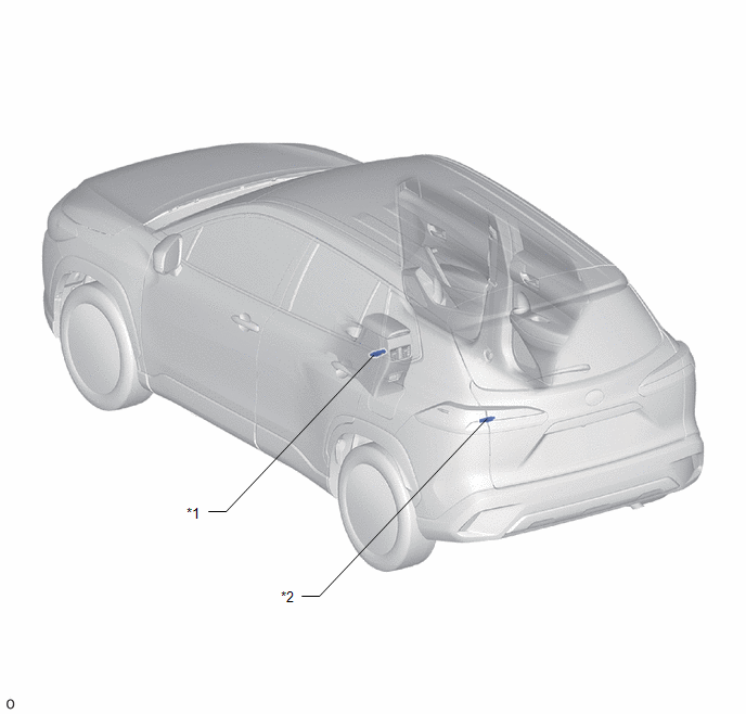
*1

NO. 1 INDOOR ELECTRICAL KEY ANTENNA ASSEMBLY (FRONT FLOOR)

*2

NO. 3 INDOOR ELECTRICAL KEY ANTENNA ASSEMBLY (INSIDE LUGGAGE COMPARTMENT)

ILLUSTRATION

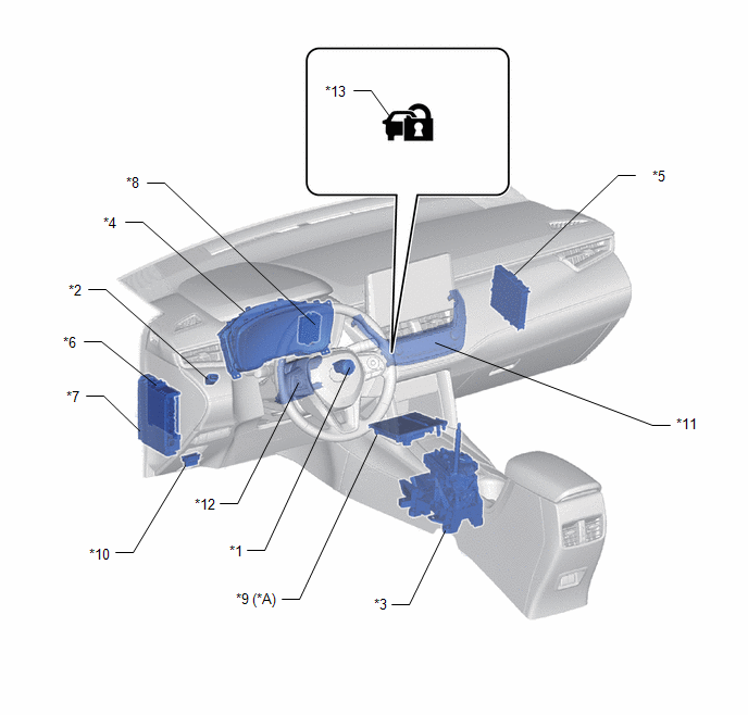
*A

w/ Wireless Charging System

-

-

*1

ENGINE SWITCH

*2

STOP LIGHT SWITCH ASSEMBLY

*3

SHIFT LOCK CONTROL UNIT ASSEMBLY

*4

COMBINATION METER ASSEMBLY

*5

CERTIFICATION ECU (SMART KEY ECU ASSEMBLY)

*6

MAIN BODY ECU (MULTIPLEX NETWORK BODY ECU)

*7

POWER DISTRIBUTION BOX ASSEMBLY

- ACC RELAY

- IGR NO. 1 RELAY

- IGR NO. 2 RELAY

- AM2 FUSE

- STOP FUSE

- ECU-ACC FUSE

- ECU-IGR NO. 1 FUSE

- ECU-IGR NO. 2 FUSE

*8

ID CODE BOX (IMMOBILISER CODE ECU)

*9

MOBILE WIRELESS CHARGER CRADLE ASSEMBLY

*10

DLC3

*11

AIR CONDITIONING CONTROL ASSEMBLY

*12

AIR CONDITIONER AMPLIFIER ASSY

*13

SECURITY INDICATOR LIGHT

-

-

    READ NEXT:

     System Diagram

    SYSTEM DIAGRAM SMART KEY SYSTEM (for Start Function) SMART KEY SYSTEM (for Entry Function) Click here

     How To Proceed With Troubleshooting

    CAUTION / NOTICE / HINT NOTICE: Do not perform "Smart Code Reset" (all key ID erasure) until all malfunctions and symptoms have been confirmed and resolved. If all key ID erasure is performed wi

     Customer Problem Analysis Check

    CUSTOMER PROBLEM ANALYSIS CHECK HINT: Be sure to ask the customer in detail about the following points concerning the vehicle operating conditions, environment and problem, and then check for DT

    SEE MORE:

     Customize Parameters

    CUSTOMIZE PARAMETERS CUSTOMIZE WIRELESS DOOR LOCK CONTROL SYSTEM NOTICE: When the customer requests a change in a function, first make sure that the function can be customized. Be sure to make a note of the current settings before customizing. When troubleshooting a function, first ma

     Starter Inrush Current Reduction Relay Circuit

    DESCRIPTION The starter inrush current reduction relay prevents the auxiliary battery voltage from becoming dropping excessively while the starter assembly is operating. If the auxiliary battery voltage drops below the threshold, stop and start control will be prohibited. In order to prevent this, t

    © 2020-2025 Copyright www.tcorollacross.com