Toyota Corolla Cross Owners & Service Manuals

Toyota Corolla Cross: Parts Location

PARTS LOCATION

ILLUSTRATION
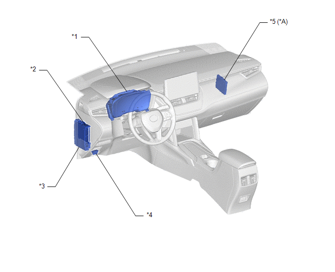
*A

w/ Smart Key System

-

-

*1

COMBINATION METER ASSEMBLY

*2

MAIN BODY ECU (MULTIPLEX NETWORK BODY ECU)

*3

POWER DISTRIBUTION BOX ASSEMBLY

- ECU-B NO. 2 FUSE

- DOOR F/L FUSE

- DOOR F/R FUSE

- DOOR R/L FUSE

- DOOR R/R FUSE

*4

DLC3

*5

CERTIFICATION ECU (SMART KEY ECU ASSEMBLY)

-

-

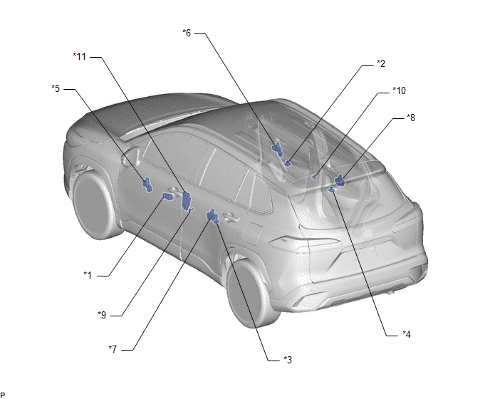
ILLUSTRATION

*1

MULTIPLEX NETWORK MASTER SWITCH ASSEMBLY

*2

POWER WINDOW REGULATOR SWITCH ASSEMBLY

*3

REAR POWER WINDOW REGULATOR SWITCH ASSEMBLY (for LH Door)

*4

REAR POWER WINDOW REGULATOR SWITCH ASSEMBLY (for RH Door)

*5

POWER WINDOW REGULATOR MOTOR ASSEMBLY (for Driver Door)

*6

POWER WINDOW REGULATOR MOTOR ASSEMBLY (for Front Passenger Door)

*7

POWER WINDOW REGULATOR MOTOR ASSEMBLY (for Rear LH Door)

*8

POWER WINDOW REGULATOR MOTORASSEMBLY (for Rear RH Door)

*9

FRONT DOOR COURTESY LIGHT SWITCH ASSEMBLY (for LH)

*10

FRONT DOOR COURTESY LIGHT SWITCH ASSEMBLY (for RH)

*11

FRONT DOOR LOCK WITH MOTOR ASSEMBLY LH

-

-

    READ NEXT:

     System Diagram

    SYSTEM DIAGRAM Communication Table Transmitting ECU Receiving ECU Signal Communication Method Multiplex Network Master Switch Assembly Power Window Regulator Motor Assembly

     How To Proceed With Troubleshooting

    CAUTION / NOTICE / HINT HINT: Use the following procedure to troubleshoot the power window control system. *: Use the GTS. PROCEDURE 1. VEHICLE BROUGHT TO WORKSHOP NEXT

     Operation Check

    OPERATION CHECK CHECK WINDOW LOCK FUNCTION HINT: Before performing the window lock switch operation check, make sure that the window lock switch is off (the switch is not pushed in). (a) Turn the w

    SEE MORE:

     Installation

    INSTALLATION CAUTION / NOTICE / HINT COMPONENTS (INSTALLATION) Procedure Part Name Code 1 INSTALL MILLIMETER WAVE RADAR SENSOR ASSEMBLY 88211B - - 2

     Terminals Of Ecu

    TERMINALS OF ECU CLEARANCE WARNING ECU ASSEMBLY (a) Disconnect the I24 clearance warning ECU assembly connector. (b) Measure the voltage and resistance on the wire harness side connector according to the value(s) in the table below. Terminal No. (Symbol) Terminal Descri

    © 2020-2024 Copyright www.tcorollacross.com