Toyota Corolla Cross Owners & Service Manuals

Toyota Corolla Cross: Parts Location

PARTS LOCATION

ILLUSTRATION
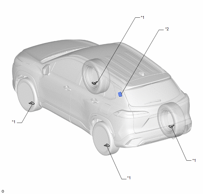
*1

TIRE PRESSURE WARNING VALVE AND TRANSMITTER

*2

TIRE PRESSURE WARNING ECU AND RECEIVER

ILLUSTRATION

*A

w/o Stop and Start System

-

-

*1

COMBINATION METER ASSEMBLY

- TIRE PRESSURE WARNING LIGHT

- MULTI-INFORMATION DISPLAY

*2

STEERING PAD SWITCH ASSEMBLY

*3

SPIRAL CABLE SUB-ASSEMBLY

*4

POWER DISTRIBUTION BOX ASSEMBLY

- ECU-IGR NO. 1 FUSE

- ECU-B NO. 2 FUSE

*5

MAIN BODY ECU (MULTIPLEX NETWORK BODY ECU)

*6

DLC3

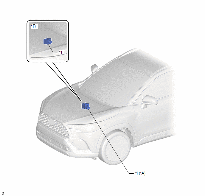
ILLUSTRATION

*A

for Gasoline Model

*B

for HEV Model

*1

SKID CONTROL ECU (BRAKE ACTUATOR ASSEMBLY)

-

-

    READ NEXT:

     System Diagram

    SYSTEM DIAGRAM

     How To Proceed With Troubleshooting

    CAUTION / NOTICE / HINT HINT: Use the following procedure to troubleshoot the tire pressure warning system. Make sure that the wireless door lock control system has exited diagnostic mode

     Operation Check

    OPERATION CHECK CHECK TIRE PRESSURE WARNING SYSTEM FUNCTION (a) Using the Data List, check that the current tire pressure is normal. Click here (1) Slowly reduce the tire pressure of the front

    SEE MORE:

     ABS Operation Continuous Request (C116E63,C116F63,C124E62)

    DESCRIPTION The skid control ECU (brake actuator assembly) measures the speed of each wheel by receiving signals from each speed sensor. These signals are used for recognizing that all four wheels are operating properly. Therefore, signals from all wheels must be equal. DTC No.

     Evaporator Temperature Sensor Circuit Short to Ground (P053511)

    DESCRIPTION The No. 1 cooler thermistor is installed to the evaporator in the air conditioner unit to detect the temperature of the cooled air that has passed through the evaporator, which is used to control the air conditioning system. It sends signals to the air conditioning amplifier assembly. Th

    © 2020-2024 Copyright www.tcorollacross.com