Toyota Corolla Cross: Parts Location
Toyota Corolla Cross (2022-2025) Service Manual / Engine & Hybrid System / M20a-fxs (fuel) / Fuel System / Parts Location
PARTS LOCATION
ILLUSTRATION

|
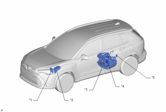
*1 | ECM |
*2 | NO. 1 ENGINE ROOM RELAY BLOCK AND NO. 1 ENGINE ROOM JUNCTION BLOCK - IG2 NO. 1 RELAY - EFI-MAIN NO. 2 RELAY - INJ FUSE |
|
*3 | FUEL TANK ASSEMBLY |
*4 | FUEL SUCTION TUBE WITH PUMP AND GAUGE ASSEMBLY - FUEL PUMP (for Low Pressure) - FUEL SENDER GAUGE ASSEMBLY - FUEL MAIN VALVE ASSEMBLY |
|
*5 | FUEL PUMP CONTROL ECU |
- | - |
ILLUSTRATION

|
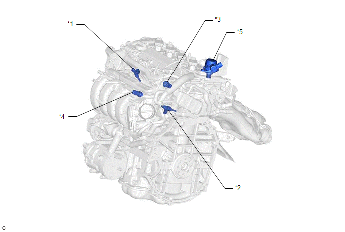
*1 | PORT FUEL INJECTOR ASSEMBLY |
*2 | DIRECT FUEL INJECTOR ASSEMBLY |
|
*3 | NO. 2 FUEL PRESSURE SENSOR (for Low Pressure) |
*4 | FUEL PRESSURE SENSOR (for High Pressure) |
|
*5 | FUEL PUMP ASSEMBLY (for High Pressure) |
- | - |


