Toyota Corolla Cross: Parts Location
PARTS LOCATION
ILLUSTRATION
|
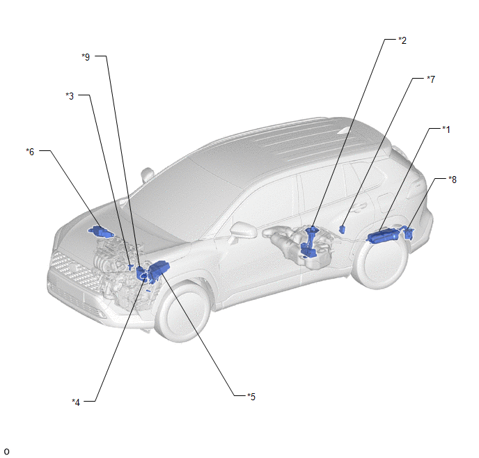
*1 | CANISTER |
*2 | FUEL PUMP (for Low Pressure Side) |
|
*3 | MASS AIR FLOW METER SUB-ASSEMBLY |
*4 | PARK / NEUTRAL POSITION SWITCH ASSEMBLY |
|
*5 | NO. 1 ENGINE ROOM RELAY BLOCK ASSEMBLY |
*6 | NO. 2 RELAY BLOCK ASSEMBLY |
|
*7 | FUEL PUMP CONTROL ECU |
*8 | CANISTER PUMP MODULE |
|
*9 | ECM |
- | - |
ILLUSTRATION
|
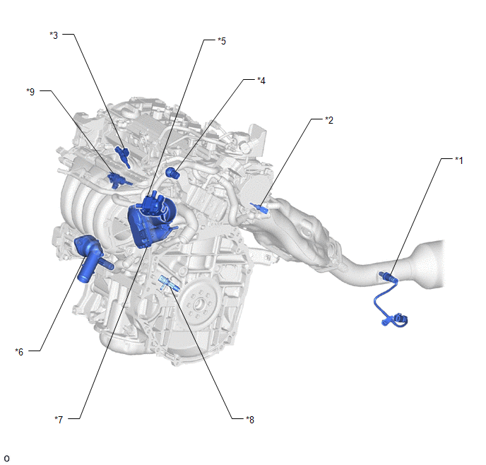
*1 | AIR FUEL RATIO SENSOR (Sensor 2) |
*2 | ENGINE COOLANT TEMPERATURE SENSOR |
|
*3 | PORT FUEL INJECTOR ASSEMBLY |
*4 | NO. 2 FUEL PRESSURE SENSOR (for Low Pressure Side) |
|
*5 | VACUUM SWITCHING VALVE (PURGE VSV) |
*6 | WATER INLET WITH THERMOSTAT SUB-ASSEMBLY |
|
*7 | THROTTLE BODY WITH MOTOR ASSEMBLY |
*8 | CRANKSHAFT POSITION SENSOR |
|
*9 | DIRECT FUEL INJECTOR ASSEMBLY |
- | - |
ILLUSTRATION
|
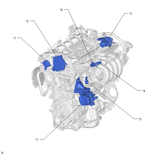
*1 | CAM TIMING OIL CONTROL SOLENOID ASSEMBLY |
*2 | CAM TIMING CONTROL MOTOR WITH EDU ASSEMBLY |
|
*3 | EGR VALVE ASSEMBLY |
*4 | FUEL PRESSURE SENSOR (for High Pressure Side) |
|
*5 | KNOCK CONTROL SENSOR |
*6 | MANIFOLD ABSOLUTE PRESSURE SENSOR |
|
*7 | ENGINE WATER PUMP ASSEMBLY (WATER INLET HOUSING) |
- | - |
ILLUSTRATION
|
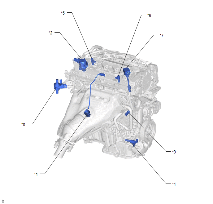
*1 | AIR FUEL RATIO SENSOR (Sensor 1) |
*2 | FUEL PUMP ASSEMBLY (for High Pressure Side) |
|
*3 | OIL PRESSURE AND TEMPERATURE SENSOR |
*4 | OIL PRESSURE CONTROL VALVE ASSEMBLY |
|
*5 | CAMSHAFT POSITION SENSOR (for Intake Camshaft) |
*6 | CAMSHAFT POSITION SENSOR (for Exhaust Camshaft) |
|
*7 | IGNITION COIL ASSEMBLY |
*8 | FLOW SHUTTING VALVE (for Heater Control) |
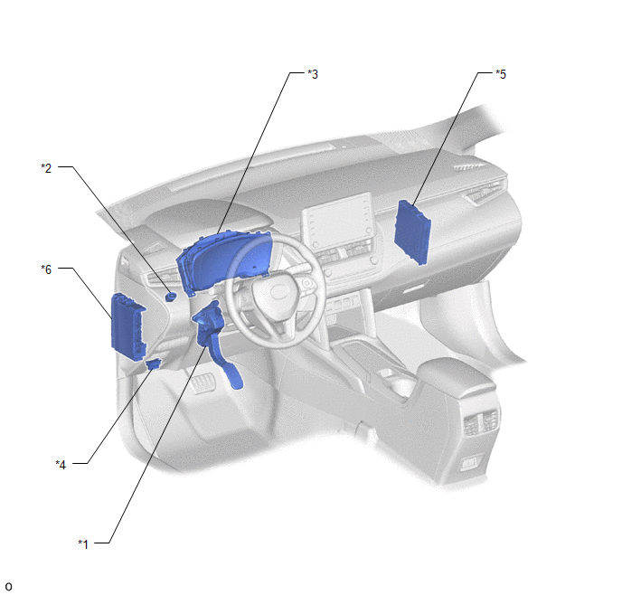
ILLUSTRATION
|
*1 | ACCELERATOR PEDAL SENSOR ASSEMBLY |
*2 | STOP LIGHT SWITCH |
|
*3 | COMBINATION METER ASSEMBLY |
*4 | DLC3 |
|
*5 | ENGINE STOP AND START ECU |
*6 | POWER DISTRIBUTION BOX ASSEMBLY |


