Toyota Corolla Cross: Parts Location
PARTS LOCATION
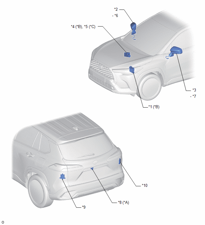
ILLUSTRATION
|
*A |
w/ Parking Assist Monitor System |
*B |
for Gasoline Model |
|
*C |
for HEV Model |
- |
- |
|
*1 |
ECM |
*2 |
OUTER REAR VIEW MIRROR ASSEMBLY RH |
|
*3 |
OUTER REAR VIEW MIRROR ASSEMBLY LH |
*4 |
BRAKE ACTUATOR ASSEMBLY (SKID CONTROL ECU) |
|
*5 |
BRAKE ACTUATOR ASSEMBLY (NO. 2 SKID CONTROL ECU) |
*6 |
OUTER MIRROR RH (OUTER REAR VIEW MIRROR INDICATOR LIGHT RH) |
|
*7 |
OUTER MIRROR LH (OUTER REAR VIEW MIRROR INDICATOR LIGHT LH) |
*8 |
REAR TELEVISION CAMERA ASSEMBLY |
|
*9 |
BLIND SPOT MONITOR SENSOR LH (B) |
*10 |
BLIND SPOT MONITOR SENSOR RH (A) |
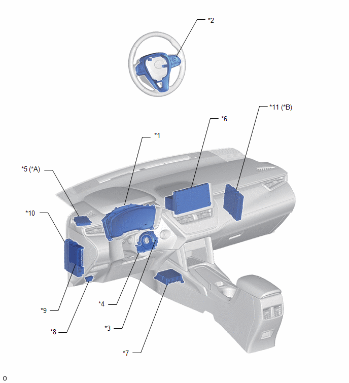
ILLUSTRATION
|
*A |
w/ Parking Support Brake System |
*B |
for HEV Model |
|
*1 |
COMBINATION METER ASSEMBLY |
*2 |
STEERING PAD SWITCH ASSEMBLY |
|
*3 |
SPIRAL CABLE SUB-ASSEMBLY |
*4 |
STEERING SENSOR |
|
*5 |
CLEARANCE WARNING ECU ASSEMBLY |
*6 |
RADIO AND DISPLAY RECEIVER ASSEMBLY |
|
*7 |
AIRBAG ECU ASSEMBLY |
*8 |
DLC3 |
|
*9 |
MAIN BODY ECU (MULTIPLEX NETWORK BODY ECU) |
*10 |
POWER DISTRIBUTION BOX ASSEMBLY - ECU-IGR NO. 1 FUSE |
|
*11 |
HYBRID VEHICLE CONTROL ECU |
- |
- |


