Toyota Corolla Cross: System Diagram
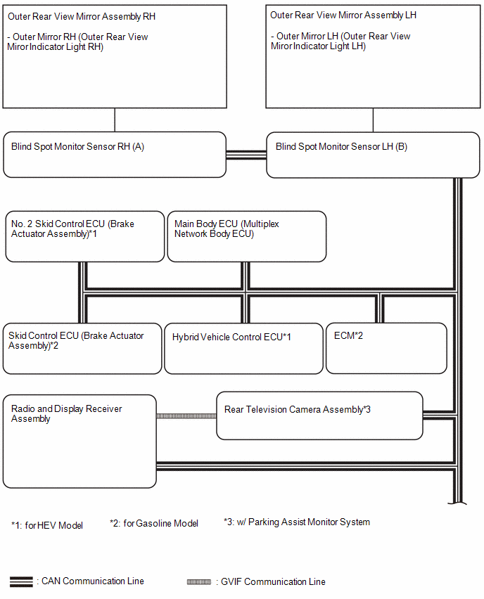
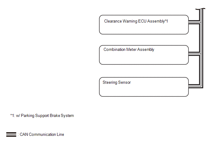
SYSTEM DIAGRAM
READ NEXT:
SYSTEM DESCRIPTION
OPERATION OF OUTER REAR VIEW MIRROR INDICATOR AND RCTA BUZZER (BLIND
SPOT MONITOR BUZZER)
(a) Initial check
(1) When the blind spot monitor system is turned on with the ignitio
CAUTION / NOTICE / HINT
HINT:
Use the following procedure to troubleshoot the blind spot monitor system.
*: Use the GTS.
PROCEDURE
1.
VEHICLE BROUGHT TO WORKSHOP
CUSTOMIZE PARAMETERS
CUSTOMIZE BLIND SPOT MONITOR SYSTEM
(a) Customizing with the GTS
NOTICE:
When the customer requests a change in a function, first make sure that
the function can be cus
SEE MORE:
INSPECTION PROCEDURE 1. INSPECT FUEL PUMP
(a) Measure the resistance according to the value(s) in the table below.
Standard Resistance:
Tester Connection Specified Condition
U - V 0.05 to 3.0 Ω
V - W 0.05 to 3.0 Ω
U - W 0.05 to 3.0 Ω
If th
OPERATION CHECK AUTOMATIC LIGHT CONTROL SYSTEM OPERATION CHECK (w/ Automatic Light Control System)
NOTICE: Make sure that the customize settings are set to default when performing the automatic light control system operation check.
Click here (a) Turn the ignition switch to ON.
(b) Turn the lig
 System Description
 Inspection
