Toyota Corolla Cross: Parking Light/Daytime Running Light Circuit
DESCRIPTION
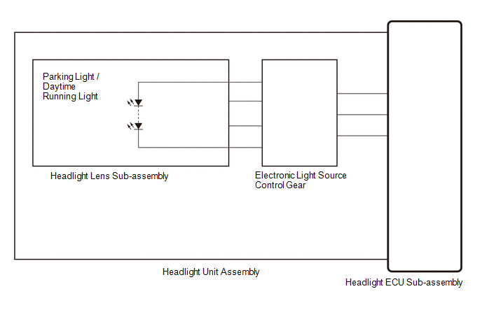
Parking light function:- When the main body ECU (multiplex network body ECU) receives the light control switch position signal, it sends an illumination request signal to the headlight ECU sub-assembly and illuminates the parking lights.
- When the operation conditions of the daytime running lights are met, the main body ECU (multiplex network body ECU) sends an illumination request signal to the headlight ECU sub-assembly and illuminates the daytime running lights.
WIRING DIAGRAM
CAUTION / NOTICE / HINT
NOTICE:
- If the headlight ECU sub-assembly LH has been replaced, it is necessary to synchronize the vehicle information and initialize the headlight ECU sub-assembly LH.
Click here
.gif)
- When replacing the headlight ECU sub-assembly LH, always replace it with a new one. If a headlight ECU sub-assembly LH which was installed to another vehicle is used, the information stored in it will not match the information from the vehicle and a DTC may be stored.
PROCEDURE
|
1. | CHECK LIGHTS |
(a) Check the illumination of each clearance lights and daytime running lights.
|
Result | Proceed to |
|---|---|
|
LH side daytime running light does not illuminate |
A |
| RH side daytime running light does not illuminate |
B |
| B |
.gif) | GO TO STEP 5 |
|
.gif)
| 2. |
PERFORM ACTIVE TEST USING GTS |
(a) Perform the Active Test according to the display on the GTS.
Body Electrical > Headlight Control > Active Test|
Tester Display | Measurement Item |
Control Range | Diagnostic Note |
|---|---|---|---|
|
Daytime Running Light | Daytime running lights |
OFF or ON | - |
|
Clearance Light (+ Front Side Marker Light) |
Parking lights and side marker lights |
OFF or ON | - |
|
Tester Display |
|---|
| Daytime Running Light |
|
Tester Display |
|---|
| Clearance Light (+ Front Side Marker Light) |
OK:
Daytime running lights illuminate.
| OK | | PROCEED TO NEXT SUSPECTED AREA SHOWN IN PROBLEM SYMPTOMS TABLE
|
|
| 3. |
CHECK HEADLIGHT UNIT ASSEMBLY LH |
(a) Interchange the headlight unit assembly LH with RH and connect the connectors.
Click here
|
| 4. |
CHECK OPERATION (PARKING LIGHTS AND DAYTIME RUNNING LIGHTS) |
(a) Check the operation of the parking light and daytime running light.
OK:
The parking lights and daytime running lights operate normally.
| OK | | REPLACE HEADLIGHT UNIT ASSEMBLY LH
|
| NG | | REPLACE HEADLIGHT ECU SUB-ASSEMBLY LH |
| 5. |
PERFORM ACTIVE TEST USING GTS |
(a) Perform the Active Test according to the display on the GTS.
Body Electrical > Headlight Control > Active Test|
Tester Display | Measurement Item |
Control Range | Diagnostic Note |
|---|---|---|---|
|
Daytime Running Light | Daytime running lights |
OFF or ON | - |
|
Clearance Light (+ Front Side Marker Light) |
Parking lights and side marker lights |
OFF or ON | - |
|
Tester Display |
|---|
| Clearance Light (+ Front Side Marker Light) |
|
Tester Display |
|---|
| Daytime Running Light |
OK:
Parking lights and daytime running lights illuminate.
| OK | | PROCEED TO NEXT SUSPECTED AREA SHOWN IN PROBLEM SYMPTOMS TABLE
|
|
| 6. |
CHECK HEADLIGHT UNIT ASSEMBLY RH |
(a) Interchange the headlight unit assembly RH with LH and connect the connectors.
Click here
|
| 7. |
CHECK OPERATION |
(a) Check the operation of the parking light and daytime running light.
OK:
The parking lights and daytime running lights operate normally.
| OK | | REPLACE HEADLIGHT UNIT ASSEMBLY RH
|
| NG | | REPLACE HEADLIGHT ECU SUB-ASSEMBLY RH |


