Toyota Corolla Cross: Back-up Light Circuit
DESCRIPTION
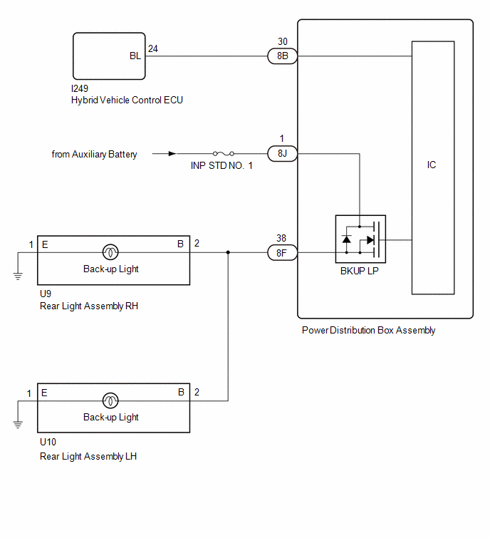
The hybrid vehicle control ECU controls the back-up lights.
WIRING DIAGRAM
CAUTION / NOTICE / HINT
NOTICE:
Inspect the fuses for circuits related to this system before performing the following procedure.
PROCEDURE
| 1. |
READ VALUE USING GTS |
(a) Turn the ignition switch to ON.
(b) Move the shift lever to R.
(c) Read the Data List according to the display on the GTS.
Body Electrical > Power Distribution Box > Data List|
Tester Display | Measurement Item |
Normal Condition | Reference Value |
Diagnostic Note |
|---|---|---|---|---|
|
Back-up Light Fuse Shut Off Status |
Back-up light fuse shut off status |
OFF or ON | OFF: Fuse has no shut off history ON: Fuse has shut off history |
- |
|
Tester Display |
|---|
| Back-up Light Fuse Shut Off Status |
OK:
The Data List value displays "OFF".
| NG | .gif) | GO TO STEP 7 |
|
.gif)
| 2. |
READ VALUE USING GTS |
(a) Read the Data List according to the display on the GTS.
Body Electrical > Power Distribution Box > Data List|
Tester Display | Measurement Item |
Normal Condition | Reference Value |
Diagnostic Note |
|---|---|---|---|---|
|
Back-up Light Input Signal |
Back-up light input | OFF or ON |
OFF: Shift lever in any position other than R ON: Shift lever in R |
- |
|
Tester Display |
|---|
| Back-up Light Input Signal |
OK:
Display changes according to shift lever operation.
| NG | | GO TO STEP 5 |
|
| 3. |
CHECK HARNESS AND CONNECTOR (POWER SOURCE - POWER DISTRIBUTION BOX ASSEMBLY) |
(a) Disconnect the 8J power distribution box assembly connector.
(b) Measure the voltage according to the value(s) in the table below.
Standard Voltage:
|
Tester Connection | Switch Condition |
Specified Condition |
|---|---|---|
|
8J-1 - Body ground | Ignition switch off |
11 to 14 V |
| NG | | REPAIR OR REPLACE HARNESS OR CONNECTOR |
|
| 4. |
CHECK HARNESS AND CONNECTOR (REAR LIGHT ASSEMBLY - POWER DISTRIBUTION BOX ASSEMBLY) |
(a) Disconnect the U9 rear light assembly RH connector.
(b) Disconnect the U10 rear light assembly LH connector.
(c) Disconnect the 8F power distribution box assembly connector.
(d) Measure the resistance according to the value(s) in the table below.
Standard Resistance:
|
Tester Connection | Condition |
Specified Condition |
|---|---|---|
|
U9-2 (B) - 8F-38 | Always |
Below 1 Ω |
|
U10-2 (B) - 8F-38 | Always |
Below 1 Ω |
| OK | | REPLACE POWER DISTRIBUTION BOX ASSEMBLY |
| NG | | REPAIR OR REPLACE HARNESS OR CONNECTOR |
| 5. |
CHECK HARNESS AND CONNECTOR (HYBRID VEHICLE CONTROL ECU - POWER DISTRIBUTION BOX ASSEMBLY) |
(a) Disconnect the I249 hybrid vehicle control ECU connector.
(b) Disconnect the 8B power distribution box assembly connector.
(c) Measure the resistance according to the value(s) in the table below.
Standard Resistance:
|
Tester Connection | Condition |
Specified Condition |
|---|---|---|
|
I249-24 (BL) - 8B-30 |
Always | Below 1 Ω |
|
I249-24 (BL) - Body ground |
Always | 10 kΩ or higher |
|
8B-30 - Body ground | Always |
10 kΩ or higher |
| NG | | REPAIR OR REPLACE HARNESS OR CONNECTOR |
|
| 6. |
CHECK HYBRID VEHICLE CONTROL ECU (OUTPUT VOLTAGE) |
| (a) Connect the I249 hybrid vehicle control ECU connector. |
|
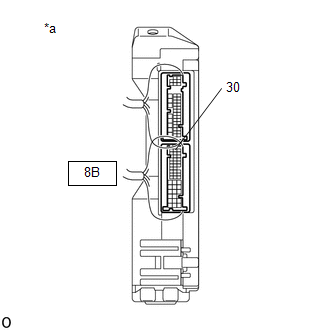
(b) Connect the 8B power distribution box assembly connector.
(c) Measure the voltage according to the value(s) in the table below.
Standard Voltage:
|
Tester Connection | Condition |
Specified Condition |
|---|---|---|
|
8B-30 - Body ground | Ignition switch ON, reverse (R) not selected |
Below 1 V |
|
8B-30 - Body ground | Ignition switch ON, reverse (R) selected |
11 to 14 V |
| OK | | REPLACE POWER DISTRIBUTION BOX ASSEMBLY |
| NG | | REPLACE HYBRID VEHICLE CONTROL ECU for 2ZR-FXE: Click here for M20A-FXS: Click here
|
.gif)
| 7. |
CHECK REAR LIGHT ASSEMBLY LH |
(a) Disconnect the U10 rear light assembly LH connector.
(b) Turn the ignition switch to ON.
(c) Move the shift lever to R.
(d) Read the Data List according to the display on the GTS.
Body Electrical > Power Distribution Box > Data List|
Tester Display | Measurement Item |
Normal Condition | Reference Value |
Diagnostic Note |
|---|---|---|---|---|
|
Back-up Light Fuse Shut Off Status |
Back-up light fuse shut off status |
OFF or ON | OFF: Fuse has no shut off history ON: Fuse has shut off history |
- |
|
Tester Display |
|---|
| Back-up Light Fuse Shut Off Status |
OK:
The Data List value displays "OFF".
| OK | | REPLACE REAR LIGHT ASSEMBLY LH |
|
| 8. |
CHECK REAR LIGHT ASSEMBLY RH |
(a) Disconnect the U9 rear light assembly RH connector.
(b) Turn the ignition switch to ON.
(c) Move the shift lever to R.
(d) Read the Data List according to the display on the GTS.
Body Electrical > Power Distribution Box > Data List|
Tester Display | Measurement Item |
Normal Condition | Reference Value |
Diagnostic Note |
|---|---|---|---|---|
|
Back-up Light Fuse Shut Off Status |
Back-up light fuse shut off status |
OFF or ON | OFF: Fuse has no shut off history ON: Fuse has shut off history |
- |
|
Tester Display |
|---|
| Back-up Light Fuse Shut Off Status |
OK:
The Data List value displays "OFF".
| OK | | REPLACE REAR LIGHT ASSEMBLY RH |
| NG | | REPAIR OR REPLACE HARNESS OR CONNECTOR |


