Toyota Corolla Cross: On-vehicle Inspection
ON-VEHICLE INSPECTION
PROCEDURE
1. INSPECT STOP LIGHT SWITCH ASSEMBLY
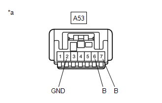
(a) Disconnect the A53 stop light switch assembly connector.
| (b) Measure the voltage and resistance on the wire harness side connector according to the value(s) in the table below.
Standard Voltage: |
Tester Connection | Condition |
Specified Condition | |
A53-7 (B) - A53-2 (GND) |
Always | 11 to 14 V | |
A53-6 (B) - A53-2 (GND) |
Ignition switch on (IG) |
11 to 14 V | Standard Resistance: |
Tester Connection | Condition |
Specified Condition | |
A53-2 (GND) - Body ground |
Always | Below 1 Ω |
If the result is not as specified, repair or replace the wire harness or connector. |
 |
|
*a | Front view of wire harness connector
(to Stop Light Switch Assembly) | | |
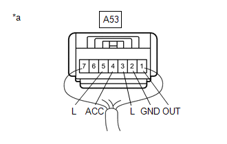
(c) Connect the A53 stop light switch assembly connector.
| (d) Measure the voltage according to the value(s) in the table below.
Standard Voltage: |
Tester Connection | Condition |
Specified Condition | |
A53-1 (OUT) - A53-2 (GND) |
Brake pedal not depressed |
Below 1 V | |
A53-1 (OUT) - A53-2 (GND) |
Brake pedal depressed |
11 to 14 V | |
A53-3 (L) - A53-2 (GND) |
Brake pedal not depressed |
Below 1 V | |
A53-3 (L) - A53-2 (GND) |
Brake pedal depressed |
11 to 14 V | |
A53-4 (ACC) - A53-2 (GND) |
Always | 11 to 14 V | |
A53-5 (L) - A53-2 (GND) |
Ignition switch on (IG), brake pedal not depressed |
11 to 14 V | |
A53-5 (L) - A53-2 (GND) |
Ignition switch on (IG), brake pedal depressed |
Below 1 V | If the result is not as specified, replace the stop light switch assembly. |
 |
|
*a | Component with harness connected
(Stop Light Switch Assembly) | | |
READ NEXT:
REMOVAL CAUTION / NOTICE / HINT COMPONENTS (REMOVAL)
Procedure Part Name Code
1 NO. 1 INSTRUMENT PANEL UNDER COVER SUB-ASSEMBLY
55606 -
- -
2 NO
INSTALLATION CAUTION / NOTICE / HINT COMPONENTS (INSTALLATION)
Procedure Part Name Code
1 STOP LIGHT SWITCH MOUNTING ADJUSTER
84345 -
- -
2 STOP
SEE MORE:
SYSTEM DESCRIPTION FUNCTION OF SRS CONNECTORS
(a) Location of activation prevention mechanism
(b) Function of activation prevention mechanism
(1) This mechanism is designed to create a short circuit automatically between the positive (+) and negative (-) terminals of a squib power source con
DESCRIPTION The combination meter assembly blinks or turns off the passenger seat belt warning light on the combination meter assembly in accordance with the state of the front seat inner belt assembly (for passenger side) and occupant detection sensor (front seat cushion pad (for passenger side)).


