Toyota Corolla Cross: Installation
INSTALLATION
CAUTION / NOTICE / HINT
COMPONENTS (INSTALLATION)
|
Procedure | Part Name Code |
.png) |
.png) |
 |
|---|---|---|---|---|---|
|
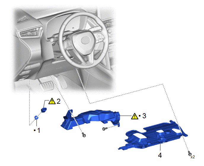
1 | STOP LIGHT SWITCH MOUNTING ADJUSTER |
84345 | - |
- | - |
|
2 | STOP LIGHT SWITCH ASSEMBLY |
84340 |
|
- | - |
|
3 | NO. 1 AIR DUCT |
87211 |
|
- | - |
|
4 | NO. 1 INSTRUMENT PANEL UNDER COVER SUB-ASSEMBLY |
55606 | - |
- | - |
|
● | Non-reusable part |
- | - |
PROCEDURE
1. INSTALL STOP LIGHT SWITCH MOUNTING ADJUSTER
2. INSTALL STOP LIGHT SWITCH ASSEMBLY

|
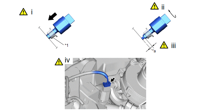
*1 | Stop light switch mounting adjuster |
- | - |
|
*a | Protrusion Amount Measurement Area |
- | - |
(1) Insert the stop light switch assembly to the stop light switch mounting adjuster until the switch body slightly touches the brake pedal.
NOTICE:
Do not depress the brake pedal.
(2) Turn the stop light switch assembly clockwise by approximately one fourth of a rotation.
Torque:
1.5 N·m {15 kgf·cm, 13 in·lbf}
(3) Check the protrusion amount of the shaft.
Protrusion amount of the shaft:
|
Area | Measurement |
Area | Measurement |
|---|---|---|---|
|
a | 0.5 to 2.6 mm (0.0197 to 0.102 in.) |
- | - |
(4) Connect the connector.
NOTICE:
Check that the stop light does not come on when the brake pedal is not depressed.
3. INSTALL NO. 1 AIR DUCT
.png) |
Click here |
4. INSTALL NO. 1 INSTRUMENT PANEL UNDER COVER SUB-ASSEMBLY

.gif)

