Toyota Corolla Cross: On-vehicle Inspection
ON-VEHICLE INSPECTION
CAUTION / NOTICE / HINT
CAUTION:
To prevent injury due to contact with an operating cooling fan, keep your hands and clothing away from the cooling fans when working in the engine compartment with the engine running or the power switch on (IG).
PROCEDURE
1. INSPECT ENGINE COOLANT (for Engine)
Click here .gif)
2. INSPECT ENGINE OIL
Click here
3. INSPECT AUXILIARY BATTERY
Click here
4. INSPECT SPARK PLUG
Click here
5. INSPECT AIR CLEANER FILTER ELEMENT SUB-ASSEMBLY
Click here
6. INSPECT VALVE LASH ADJUSTER ASSEMBLY NOISE
(a) Put the engine in inspection mode.
Click here
(b) Rev up the engine several times. Check that the engine does not emit unusual noises.
(c) If unusual noises occur, warm up the engine and idle it for 30 minutes or more, then perform the inspection.
HINT:
If any defects or problems are found during the inspection, perform the valve lash adjuster assembly inspection.
Click here
7. INSPECT IGNITION TIMING
NOTICE:
- Check the ignition timing with the cooling fan off.
- Turn off all electrical systems and the A/C.
- When checking the ignition timing, the transaxle should be in park.
(a) Put the engine in inspection mode.
Click here
(b) Warm up and stop the engine.
(c) Connect the GTS to the DLC3.
(d) Put the engine in inspection mode.
Click here
(e) Enter the following menus: Powertrain / Engine / Data List / Ignition Timing Cylinder #1.
Powertrain > Engine > Data List|
Tester Display |
|---|
| Ignition Timing Cylinder #1 |
Standard Ignition Timing:
0 to 15° BTDC at idle
(f) Check that the ignition timing advances immediately when the engine speed is increased.
(g) Enter the following menus: Powertrain / Engine / Active Test / Activate the TC Terminal / ON.
Powertrain > Engine > Active Test|
Active Test Display |
|---|
|
Activate the TC Terminal |
|
Data List Display |
|---|
|
Ignition Timing Cylinder #1 |
(h) Monitor Ignition Timing Cylinder #1 of the Data List.
Standard Ignition Timing:
8 to 12° BTDC at idle
8. INSPECT ENGINE IDLE SPEED
NOTICE:
- Check the ignition timing with the cooling fan off.
- Turn off all electrical systems and the A/C.
- When checking the ignition timing, the transaxle should be in park.
(a) Put the engine in inspection mode.
Click here
(b) Warm up and stop the engine.
(c) Put the engine in inspection mode.
Click here
(d) Enter the following menus: Powertrain / Engine / Data List / Engine Speed.
Powertrain > Engine > Data List|
Tester Display |
|---|
| Engine Speed |
(e) Read the value displayed on the GTS.
Standard Idle Speed:
950 to 1050 rpm
9. INSPECT COMPRESSION
NOTICE:
Keep the spark plug holes free of foreign matter when measuring the compression pressure.
(a) Put the engine in inspection mode.
Click here
(b) Warm up and stop the engine.
(c) Check for DTCs.
Click here
(d) Remove the air cleaner cap with air cleaner hose.
Click here
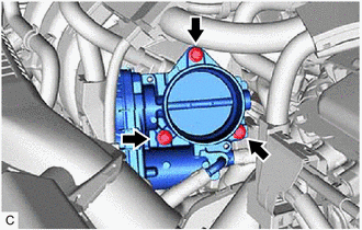
| (e) Using an 8 mm socket wrench, remove the 3 bolts to separate the throttle body with motor assembly from the intake manifold. |
|
(f) Remove the 4 spark plugs.
Click here
NOTICE:
DTCs will be stored if the inspection is performed with the ignition coil assembly connectors disconnected. Make sure that the ignition coil assembly connectors are connected during the inspection.
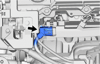
| (g) Disconnect the No. 5 engine wire connector. |
|
(h) Remove the No. 1 engine under cover assembly.
Click here
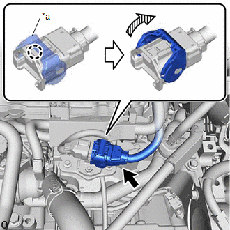
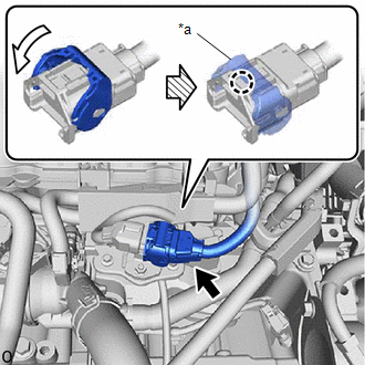
| (i) Disengage the claw and raise the lock lever to disconnect the No. 6 engine wire connector as shown in the illustration. |
|
| (j) Check the cylinder compression pressure. (1) Insert a compression gauge into the spark plug hole. (2) Connect the GTS to the DLC3. (3) Turn the power switch on (IG). (4) Turn the GTS on. NOTICE: Check the HV battery voltage in the Data List to ensure that the battery is fully charged. (5) Enter the following menus: Powertrain / Hybrid Control / Active Test / Compression Test / ON. Powertrain > Hybrid Control > Active Test
(6) Depress and hold the brake pedal, and turn the power switch on (READY). Then check the compression pressure. Standard Compression Pressure: 1400 kPa (14.3 kgf/cm2, 203 psi) Minimum Compression Pressure: 800 kPa (8.2 kgf/cm2, 116 psi) Pressure Difference between Each Cylinder: 200 kPa (2.0 kgf/cm2, 29 psi) or less NOTICE:
(7) If the cylinder compression pressure is low, pour a small amount of engine oil into the cylinder through the spark plug hole and inspect it again. HINT:
|
|
.png)
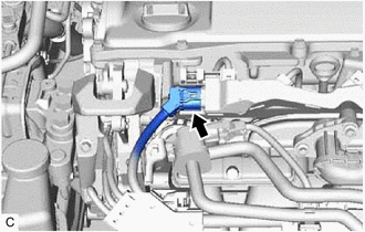
| (k) Connect the No. 6 engine wire connector and push down the lock lever to engage the claw as shown in the illustration. |
|
(l) Install the No. 1 engine under cover assembly.
Click here
| (m) Connect the No. 5 engine wire connector. |
|
(n) Install the 4 spark plugs.
Click here
NOTICE:
After performing the inspection, clear the DTCs and confirm that DTCs are not stored again or that the normal system code is output if using a check wire.
(o) Using an 8 mm socket wrench, install the throttle body with motor assembly to the intake manifold with the 3 bolts.
Torque:
10 N·m {102 kgf·cm, 7 ft·lbf}
(p) Install the air cleaner cap with air cleaner hose.
Click here
(q) Clear the DTCs.
Click here
NOTICE:
After performing the inspection, clear the DTCs and confirm that DTCs are not stored again or that the normal system code is output if using a check wire.
10. INSPECT CO/HC
HINT:
This check determines whether or not the idle CO/HC complies with regulations.
(a) Put the engine in inspection mode.
Click here
(b) Run the engine speed at 2500 rpm for approximately 180 seconds.
(c) Insert a CO/HC meter testing probe at least 40 cm (1.31 ft.) into the tailpipe during idle.
(d) Immediately check the CO/HC concentration at idle and then at an engine speed of 2500 rpm.
HINT:
When performing a 2 mode test (with the engine idling/running at 2500 rpm), the measurement procedures are determined by applicable local regulations.
If the CO/HC concentration does not comply with the regulations, perform troubleshooting in the order given below.
(1) Check for DTCs.
Click here
(2) See the following table for possible causes, then inspect the applicable parts and repair them if necessary.
|
CO | HC |
Problem | Cause |
|---|---|---|---|
|
Normal | High |
Rough idle |
|
| Low |
High | Rough idle (Fluctuating HC reading) |
|
| High |
High | Rough idle (Black smoke from exhaust) |
|


