Toyota Corolla Cross: On-vehicle Inspection
ON-VEHICLE INSPECTION
CAUTION / NOTICE / HINT
HINT:
- Use the same procedure for the RH side and LH side.
- The following procedure is for the LH side.
PROCEDURE
1. REMOVE FRONT WHEEL
Click here .gif)
2. SEPARATE FRONT DISC BRAKE CALIPER ASSEMBLY
Click here
3. REMOVE FRONT DISC
Click here
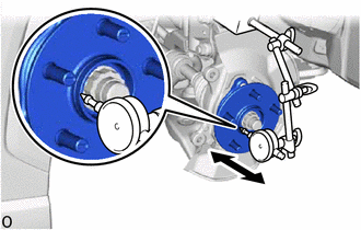
4. INSPECT FRONT AXLE HUB BEARING LOOSENESS
|
(a) Using a dial indicator with magnetic base, check for looseness near
the center of the front axle hub sub-assembly.
Maximum Looseness:
0.05 mm (0.00197 in.)
NOTICE:
- Ensure that the dial indicator is set perpendicular to the measurement
surface.
- Keep the magnet of the dial indicator away from the front axle hub
sub-assembly and front speed sensor.
|
|
(b) If the looseness exceeds the maximum, replace the front axle hub sub-assembly.
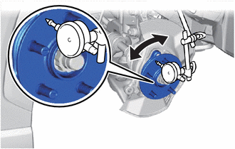
5. INSPECT FRONT AXLE HUB RUNOUT
|
(a) Using a dial indicator with magnetic base, check for runout on the
surface of the front axle hub sub-assembly outside the front axle hub bolts.
Maximum Runout:
0.05 mm (0.00197 in.)
NOTICE:
- Ensure that the dial indicator is set perpendicular to the measurement
surface.
- Make sure to set the tip of the dial indicator towards the outside
of the front axle hub bolts.
- Keep the magnet of the dial indicator away from the front axle hub
sub-assembly and front speed sensor.
|
|
(b) If the runout exceeds the maximum, replace the front axle hub sub-assembly.
6. INSTALL FRONT DISC
Click here
7. INSTALL FRONT DISC BRAKE CALIPER ASSEMBLY
Click here
8. INSTALL FRONT WHEEL
Click here
READ NEXT:
REMOVAL
CAUTION / NOTICE / HINT
COMPONENTS (REMOVAL)
Procedure
Part Name Code
1
FRONT WHEEL
-
-
INSTALLATION
CAUTION / NOTICE / HINT
COMPONENTS (INSTALLATION)
Procedure
Part Name Code
1
FRONT AXLE HUB SUB-ASSEMBLY
Components
COMPONENTS
ILLUSTRATION
*1
FRONT AXLE HUB BOLT
*2
FRONT DISC
*3
FRONT DISC BRAKE CALIPER ASSEMBLY
-
SEE MORE:
DESCRIPTION The vehicle approaching speaker assembly circuit consists of the vehicle approaching speaker controller and vehicle approaching speaker assembly.
This DTC is stored when a malfunction is detected in the vehicle approaching speaker assembly circuit or vehicle approaching speaker controll
MONITOR DESCRIPTION The ECM continuously monitors its internal memory status. This self-check ensures that the ECM is functioning properly. The ECM memory status is diagnosed by internal mirroring of the main CPU and sub CPU to detect Random Access Memory (RAM) errors. If outputs from these CPUs are