Toyota Corolla Cross: Removal
REMOVAL
CAUTION / NOTICE / HINT
COMPONENTS (REMOVAL)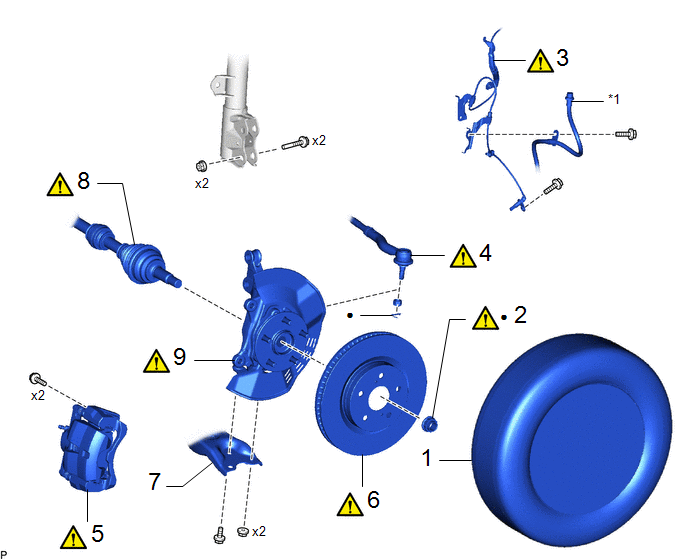
|
Procedure |
Part Name Code |
.png) |
.png) |
.png) |
|
|---|---|---|---|---|---|
|
1 |
FRONT WHEEL |
- |
- |
- |
- |
|
2 |
FRONT AXLE SHAFT NUT |
43502H |
|
- |
- |
|
3 |
FRONT SPEED SENSOR |
89543 |
|
- |
- |
|
4 |
TIE ROD END SUB-ASSEMBLY |
45047 |
|
- |
- |
|
5 |
FRONT DISC BRAKE CALIPER ASSEMBLY |
- |
|
- |
- |
|
6 |
FRONT DISC |
43512 |
|
- |
- |
|
7 |
FRONT LOWER NO. 1 SUSPENSION ARM SUB-ASSEMBLY |
48069 |
- |
- |
- |
|
8 |
FRONT DRIVE SHAFT ASSEMBLY |
43420 |
|
- |
- |
|
9 |
FRONT AXLE ASSEMBLY |
- |
|
- |
- |
|
*1 |
FRONT FLEXIBLE HOSE |
- |
- |
|
● |
Non-reusable part |
- |
- |
|
Procedure |
Part Name Code |
|
|
|
|
|---|---|---|---|---|---|
|
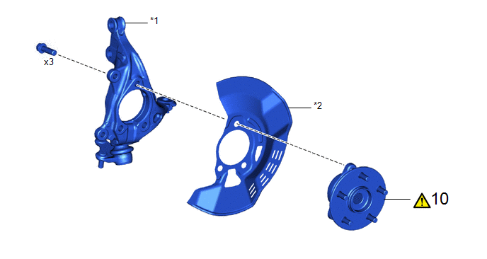
10 |
FRONT AXLE HUB SUB-ASSEMBLY |
43502C |
|
- |
- |
|
*1 |
STEERING KNUCKLE |
*2 |
FRONT DISC BRAKE DUST COVER |
CAUTION / NOTICE / HINT
The necessary procedures (adjustment, calibration, initialization, or registration) that must be performed after parts are removed and installed, or replaced during the front axle hub sub-assembly removal/installation are shown below.
Necessary Procedures After Procedure Performed|
Replaced Part or Performed Procedure |
Necessary Procedure |
Effect/Inoperative Function when Necessary Procedure not Performed |
Link |
|---|---|---|---|
|
Front wheel alignment adjustment |
for HEV Model:
|
|
|
for Gasoline Model:
|
|
|
|
for Gasoline Model AWD:
|
Dynamic torque control AWD system |
|
|
|
Suspension, tires, etc. |
Rear television camera assembly optical axis (Back camera position setting) |
Parking Assist Monitor System |
|
|
Initialize headlight ECU subassembly LH |
Automatic headlight beam level control system |
|
HINT:
- Use the same procedure for the RH side and LH side.
- The following procedure is for the LH side.
PROCEDURE
1. REMOVE FRONT WHEEL
Click here .gif)
2. REMOVE FRONT AXLE SHAFT NUT
|
|
|
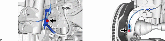
3. SEPARATE FRONT SPEED SENSOR
|
|
NOTICE:
|
4. SEPARATE TIE ROD END SUB-ASSEMBLY
|
|
Click here |
5. SEPARATE FRONT DISC BRAKE CALIPER ASSEMBLY
|
|
Click here |
6. REMOVE FRONT DISC
|
|
Click here |
7. SEPARATE FRONT LOWER NO. 1 SUSPENSION ARM SUB-ASSEMBLY

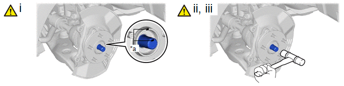
8. SEPARATE FRONT DRIVE SHAFT ASSEMBLY
|
*a |
Matchmark |
- |
- |
(1) Put matchmarks on the front drive shaft assembly and the front axle hub sub-assembly.
(2) Using a plastic hammer, separate the front drive shaft assembly from the front axle assembly.
NOTICE:
- Do not damage the front drive shaft outboard joint boot.
- Do not push the front axle assembly towards the outside of the vehicle any further than necessary.
(3) Be sure to separate the front speed sensor and front flexible hose from the front shock absorber assembly completely.
9. REMOVE FRONT AXLE ASSEMBLY
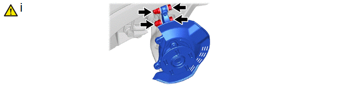
(1) Remove the 2 bolts, 2 nuts and front axle assembly from the front shock absorber assembly.
NOTICE:
When removing the nuts, keep the bolts from rotating.
10. REMOVE FRONT AXLE HUB SUB-ASSEMBLY
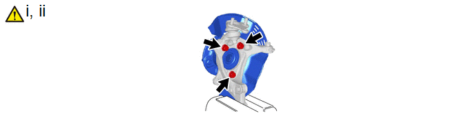
(1) Secure the front axle assembly between aluminum plates in a vise.
NOTICE:
Do not overtighten the vise.
(2) Remove the 3 bolts, front axle hub sub-assembly and front disc brake dust cover from the steering knuckle.
NOTICE:
- Do not drop the front axle hub sub-assembly.
- Be careful not to damage the speed sensor rotor or contact surfaces.
- Do not allow foreign matter to contact the speed sensor rotor or contact surfaces.


