Toyota Corolla Cross: Multi-axis Acceleration Sensor Module "A" Supply Voltage (2WD) Circuit Voltage Out of Range (C11791C,C14D71C)
DESCRIPTION
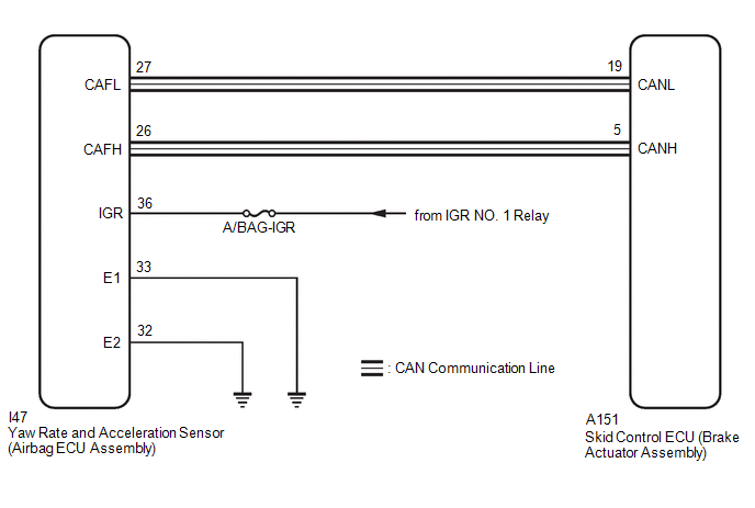
The airbag ECU assembly has a built-in yaw rate and acceleration sensor and detects the vehicle condition.
This DTC is stored when the skid control ECU (brake actuator assembly) receives a sensor supply voltage malfunction signal from the yaw rate and acceleration sensor (airbag ECU assembly).
|
DTC No. |
Detection Item |
DTC Detection Condition |
Trouble Area |
Note |
|---|---|---|---|---|
|
C11791C |
Multi-axis Acceleration Sensor Module "A" Supply Voltage (2WD) Circuit Voltage Out of Range |
Vehicle speed is 6 km/h (4 mph) or more and yaw rate and acceleration sensor power supply malfunction signal is received for 1 second or more. |
|
for 2WD |
|
C14D71C |
Multi-axis Acceleration Sensor Module "A" Supply Voltage Circuit Voltage Out of Range |
Vehicle speed is 6 km/h (4 mph) or more and yaw rate and acceleration sensor power supply malfunction signal is received for 1 second or more. |
|
for AWD |
WIRING DIAGRAM
CAUTION / NOTICE / HINT
NOTICE:
- Inspect the fuses for circuits related to this system before performing the following procedure.
- When removing/installing a supplemental restraint systems related component,
disconnect the cable from the negative (-) auxiliary battery terminal before
performing the procedure.
Click here
.gif)
PROCEDURE
|
1. |
CHECK HARNESS AND CONNECTOR (POWER SOURCE TERMINAL) |
|
(a) Disconnect the cable from the negative (-) auxiliary battery terminal. CAUTION: Wait at least 60 seconds after disconnecting the cable from the negative (-) auxiliary battery terminal to disable the SRS system. Click here
|
|
(b) Make sure that there is no looseness at the locking part and the connecting part of the connector.
OK:
The connector is securely connected.
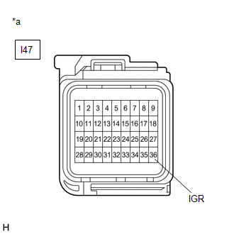
(c) Disconnect the I47 yaw rate and acceleration sensor (airbag ECU assembly) connector.
(d) Check both the connector case and the terminals for deformation and corrosion.
OK:
No deformation or corrosion.
(e) Connect the cable to the negative (-) auxiliary battery terminal.
(f) Turn the ignition switch to ON.
(g) Operate all the components of the electrical system (defogger, wipers, headlights, heater blower, etc.).
(h) Measure the voltage according to the value(s) in the table below.
Standard Voltage:
|
Tester Connection |
Condition |
Specified Condition |
|---|---|---|
|
I47-36 (IGR) - Body ground |
Ignition switch ON |
8 to 16 V |
| NG | .gif)
|
REPAIR OR REPLACE HARNESS OR CONNECTOR |
|
.gif)
|
2. |
CHECK HARNESS AND CONNECTOR (GROUND TERMINAL) |
(a) Turn the ignition switch off.
(b) Disconnect the cable from the negative (-) auxiliary battery terminal.
CAUTION:
Wait at least 60 seconds after disconnecting the cable from the negative (-) auxiliary battery terminal to disable the SRS system.
Click here
(c) Make sure that there is no looseness at the locking part and the connecting part of the connector.
OK:
The connector is securely connected.
(d) Disconnect the I47 yaw rate and acceleration sensor (airbag ECU assembly) connector.
(e) Check both the connector case and the terminals for deformation and corrosion.
OK:
No deformation or corrosion.
(f) Measure the resistance according to the value(s) in the table below.
Standard Resistance:
|
Tester Connection |
Condition |
Specified Condition |
|---|---|---|
|
I47-33 (E1) - Body ground |
1 minute or more after disconnecting the cable from the negative (-) auxiliary battery terminal |
Below 1 Ω |
|
I47-32 (E2) - Body ground |
1 minute or more after disconnecting the cable from the negative (-) auxiliary battery terminal |
Below 1 Ω |
| OK |
|
REPLACE AIRBAG ECU ASSEMBLY |
| NG |
|
REPAIR OR REPLACE HARNESS OR CONNECTOR |
READ NEXT:
 Brake System Control Module "A" System Voltage Line Internal Electronic Failure
(C117A49,C137BA2)
Brake System Control Module "A" System Voltage Line Internal Electronic Failure
(C117A49,C137BA2)
DESCRIPTION
If a malfunction is detected in the power supply circuit, the
skid control ECU (brake actuator assembly) stores this DTC and the fail-safe function
prohibits ABS operation.
This DTC
Brake Pressure Sensor "A" / Brake Switch "A" Signal Compare Failure (C117B62)
DESCRIPTION
The skid control ECU (brake actuator assembly) receives stop
light switch assembly signals and uses them to determine whether or not the brakes
are applied.
When the brake pedal is d
ECM Communication (C124A00)
DESCRIPTION
If the vehicle information stored by the skid control ECU (brake
actuator assembly) does not match that sent from the ECM or a new skid control ECU
(brake actuator assembly) is instal
SEE MORE:
 Installation
INSTALLATION CAUTION / NOTICE / HINT COMPONENTS (INSTALLATION)
Procedure Part Name Code
1 REAR CENTER SEAT OUTER BELT ASSEMBLY
73350C -
- -
2 REAR SEATBACK FRAME SUB-ASSEMBLY
71017 -
- -
Tightening torque
Power Steering ECU Communication Stop Mode
DESCRIPTION
Detection Item
Symptom
Trouble Area
Power Steering ECU Communication Stop Mode
Communication stop for "Power Steering (EPS)" is indicated on the "Communication
Bus Check" screen of the GTS.
Click her
