Toyota Corolla Cross: M20a-fks Auxiliary Battery
Installation
INSTALLATION
CAUTION / NOTICE / HINT
COMPONENTS (INSTALLATION)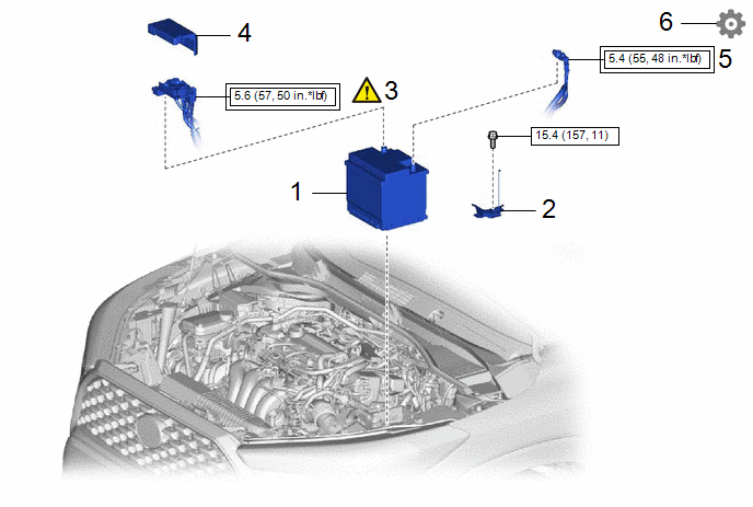
|
Procedure |
Part Name Code |
.png) |
.png) |
.png) |
|
|---|---|---|---|---|---|
|
1 |
AUXILIARY BATTERY |
- |
- |
- |
- |
|
2 |
NO. 2 BATTERY CLAMP |
74482 |
- |
- |
- |
|
3 |
POSITIVE AUXILIARY BATTERY TERMINAL |
- |
|
- |
- |
|
4 |
FUSIBLE LINK COVER |
- |
- |
- |
- |
|
5 |
NEGATIVE AUXILIARY BATTERY TERMINAL |
- |
- |
- |
- |
|
6 |
INITIALIZATION AFTER RECONNECTING AUXILIARY BATTERY TERMINAL |
- |
- |
- |
|
.png) |
Tightening torque for "Major areas involving basic vehicle performance such as moving/turning/stopping" : N*m (kgf*cm, ft.*lbf) |
.png) |
N*m (kgf*cm, ft.*lbf): Specified torque |
CAUTION / NOTICE / HINT
NOTICE:
When replacing the battery, use a new battery of the same dimensions and same capacity or more from the same class at a 20-hour rate.
PROCEDURE
1. INSTALL AUXILIARY BATTERY
2. INSTALL NO. 2 BATTERY CLAMP
Torque:
15.4 N·m {157 kgf·cm, 11 ft·lbf}
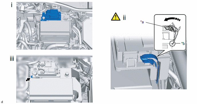
3. CONNECT POSITIVE AUXILIARY BATTERY TERMINAL
|
*a |
Locked Position |
*b |
Engage here |
.png) |
Install in this Direction |
- |
- |
(1) Connect the cable to the positive (+) battery terminal.
(2) Engage the spring assembly as shown in the illustration.
(3) Tighten the nut.
Torque:
5.6 N·m {57 kgf·cm, 50 in·lbf}
4. INSTALL FUSIBLE LINK COVER
5. CONNECT CABLE FROM NEGATIVE AUXILIARY BATTERY TERMINAL
Torque:
5.4 N·m {55 kgf·cm, 48 in·lbf}
6. INITIALIZATION AFTER RECONNECTING AUXILIARY BATTERY TERMINAL
HINT:
When disconnecting and reconnecting the auxiliary battery, there is an automatic learning function thatcompletes learning when the respective system is used.
Click here .gif)


